System for a Vehicle with Redundant Computers

a technology of computer system and vehicle, applied in the direction of process and machine control, aircraft navigation control, instruments, etc., to achieve the effect of reducing the complexity of the electronic system and the weight and power consumption of the vehicl

Active Publication Date: 2015-10-01
AIRBUS DEFENCE & SPACE
View PDF7 Cites 13 Cited by
  • Summary
  • Abstract
  • Description
  • Claims
  • Application Information

AI Technical Summary

Benefits of technology

[0004]Exemplary embodiments are directed to reducing weight and power consumption and electronic system complexity of a vehicle, as well as providing a failsafe control and management system of a vehicle.

Problems solved by technology

Furthermore, the system comprises at least two redundant computers for controlling and / or managing the vehicle.

Method used


Image

  • System for a Vehicle with Redundant Computers
  • System for a Vehicle with Redundant Computers
  • System for a Vehicle with Redundant Computers

Examples


Embodiment Construction

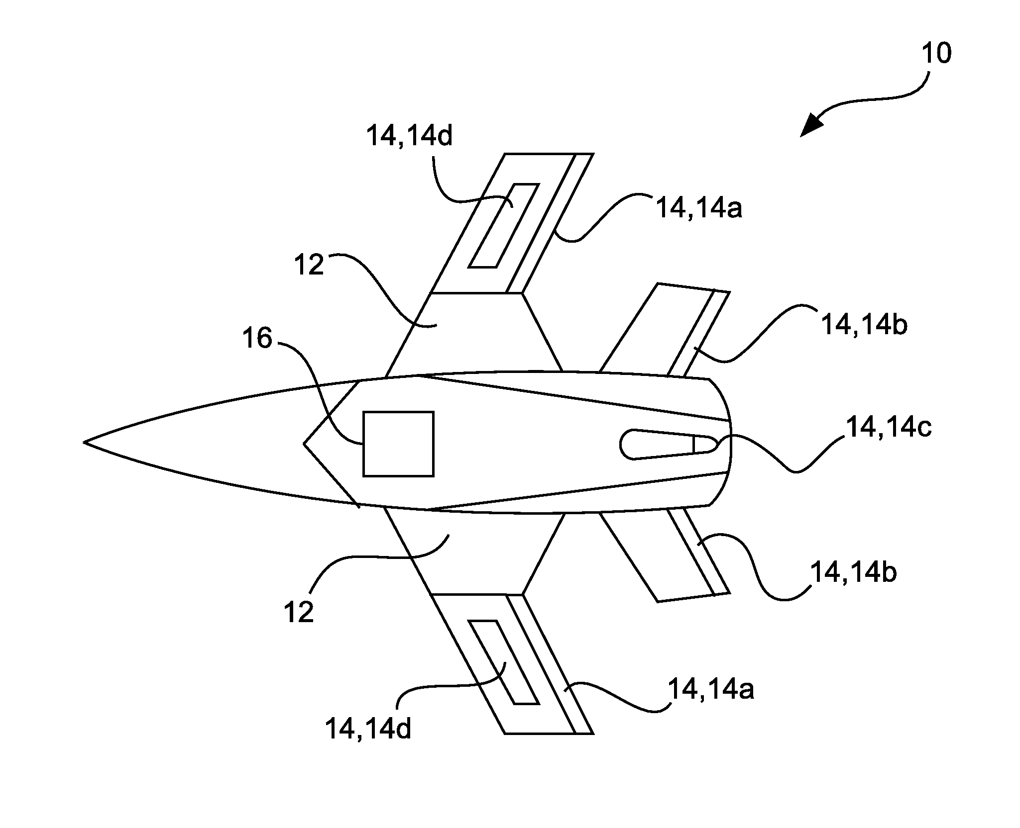
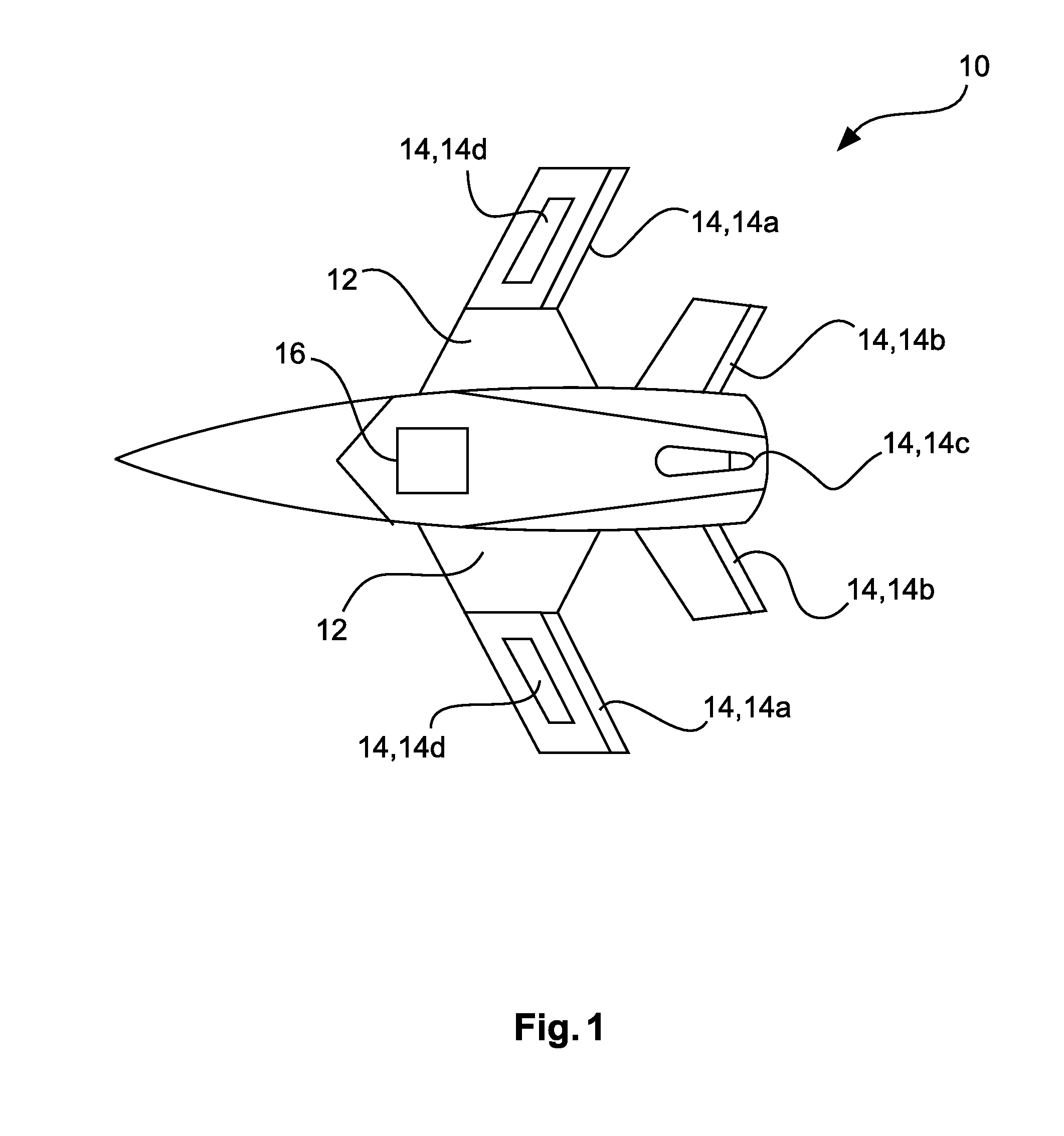
[0041]FIG. 1 shows an unmanned aerial vehicle 10 that is adapted to autonomously fly long distances and perform task without continuous support from a base station. In the illustrated example, the unmanned vehicle 10 is a plane with two wings 12. The flight of the unmanned aerial vehicle 10 is maneuvered using a set of primary control surfaces 14. Usually, these surfaces comprise a pair of ailerons 14a on the wings 12 for roll control, a pair of elevators 14b or a single elevator on the tail for pitch control and a rudder 14c on the tail for yaw control. In addition, a set of spoilers 14d may be attached to the wings for speed and roll control.

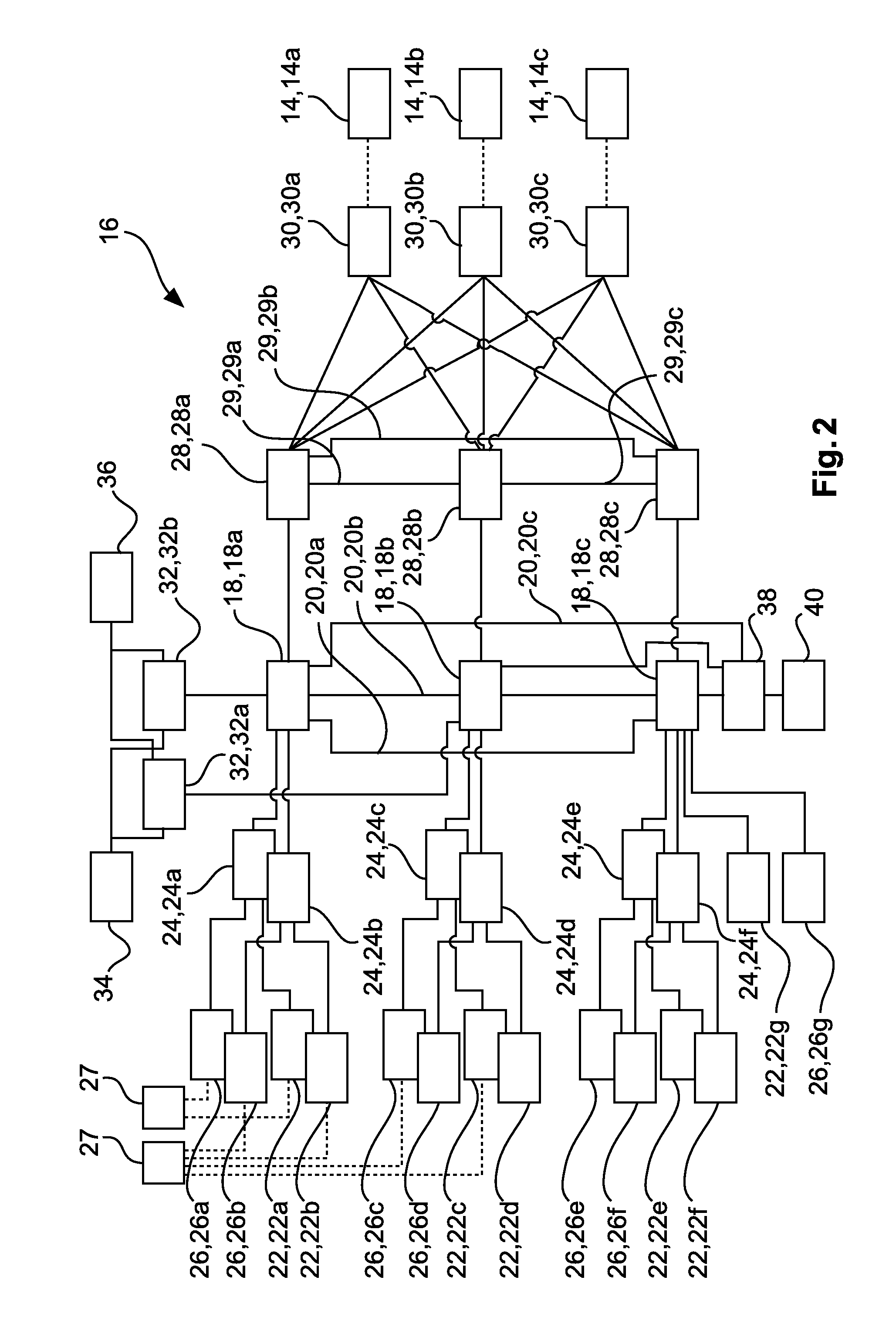
[0042]The unmanned aerial vehicle 10 and the control surfaces 14 are controlled by a control and management system 16, which will be explained with respect to FIG. 2. The following description concentrates on the application within an unmanned aerial vehicle 10 but this does not exclude other vehicle types. For example, the system 16 also may ...


PUM


Abstract

A control and/or management system for a vehicle includes at least one of: (A) at least two redundant vehicle management computers configured to generate system control commands for each maneuvering actuators and for each system actor based on the data acquired by the sensors; (B) at least two redundant remote interface units for interconnecting a sensor or a system actor with a vehicle management computer; (C) at least two redundant actuator control computers configured to generate control commands for each maneuvering actuator based on received maneuvering commands; and (D) a common interface for connecting an external computer, the common interface being directly connected to at least two redundant computers.

Description

CROSS-REFERENCE TO RELATED APPLICATIONS[0001]The present application claims priority under 35 U.S.C. §119 to European Application 14 001 107.3-1802, filed Mar. 26, 2014, the entire disclosure of which is herein expressly incorporated by reference.FIELD OF THE INVENTION[0002]Exemplary embodiments of the present invention relate to a control and / or management system for a vehicle and an unmanned aerial or ground vehicle.BACKGROUND OF THE INVENTION[0003]In particular, a long endurance unmanned aerial vehicle may have to be highly optimized with respect to its shape, weight, fuel consumption, etc. to achieve the required time on station. As a consequence there are only small control surfaces (such as ailerons and rudders) attached and there is only little space and limited electrical power available for the vehicle management, the system services, the communication and the mission avionics systems.SUMMARY OF THE INVENTION[0004]Exemplary embodiments are directed to reducing weight and po...

Claims


Application Information

Patent Timeline
Patent Type & Authority Applications(United States)
IPC IPC(8): B64C39/02B64C15/00G05D1/00
CPCB64C39/024G05D1/0011B64C2201/141B64C2201/146B64C15/00G05D1/0077B64U2201/10B64U2201/20
Inventor HEUSINGER, HUGOLOHMILLER, WINFRIEDREISCHL, REINHARDJARASCH, GREGORDELGADO ROMERO, ROSA MARIA
Owner AIRBUS DEFENCE & SPACE
Why Eureka
Try Eureka