Optical device and image display apparatus
- Summary
- Abstract
- Description
- Claims
- Application Information
AI Technical Summary
Benefits of technology
Problems solved by technology
Method used
Image
Examples
first embodiment
[0055]A description will first be made of an optical path deflecting device using an optical device according to a first embodiment of the invention and a projector using an image display apparatus according to the first embodiment of the invention.
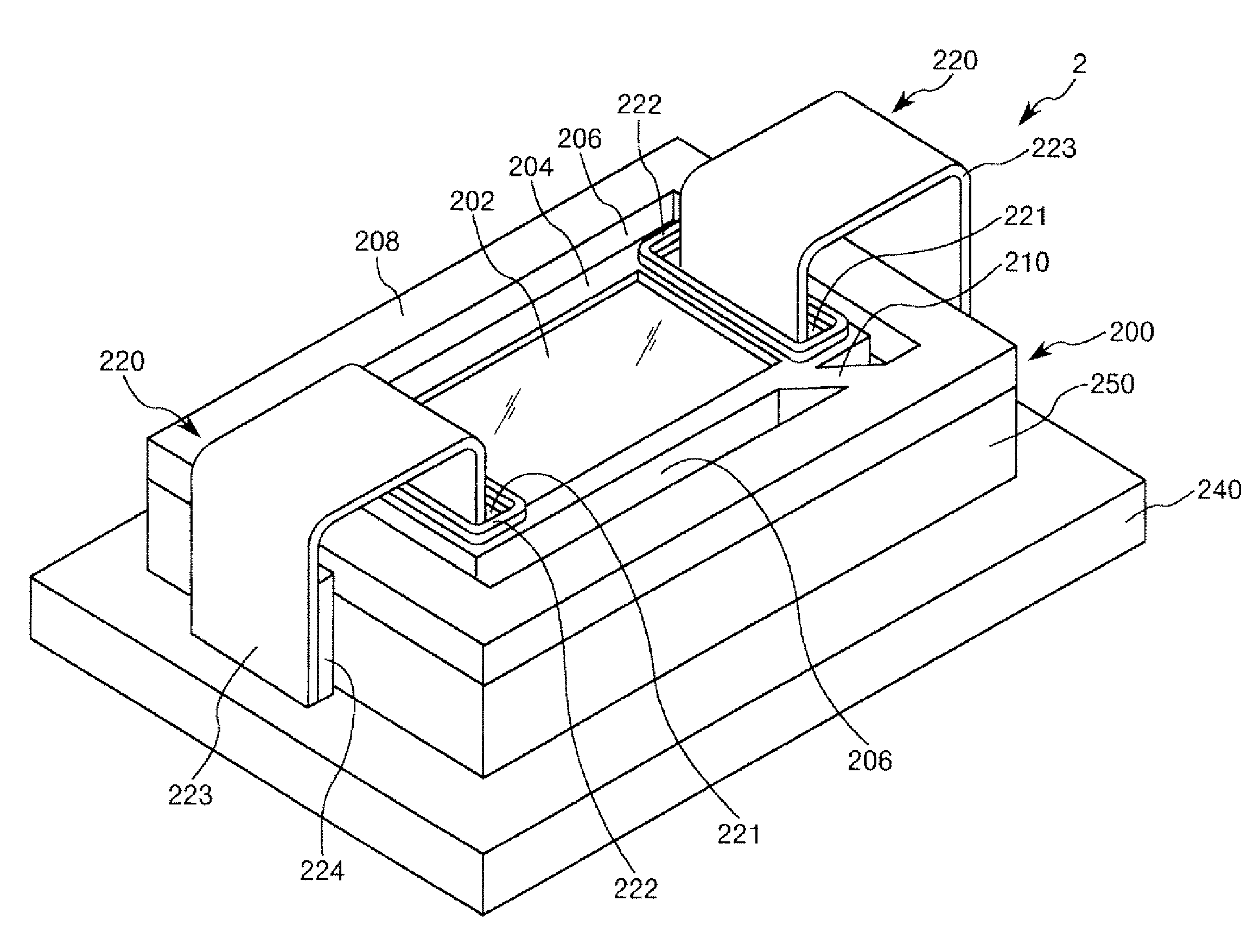
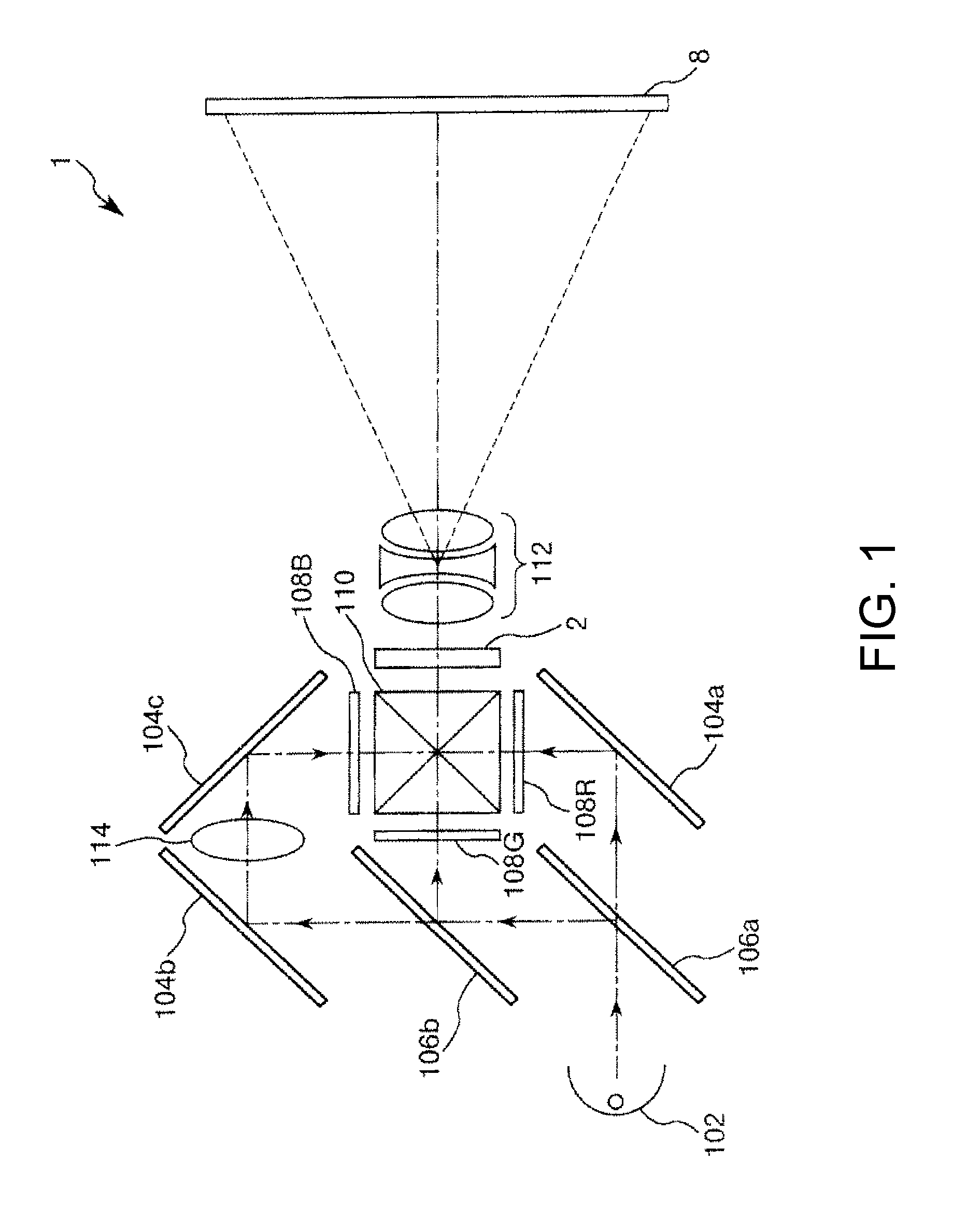
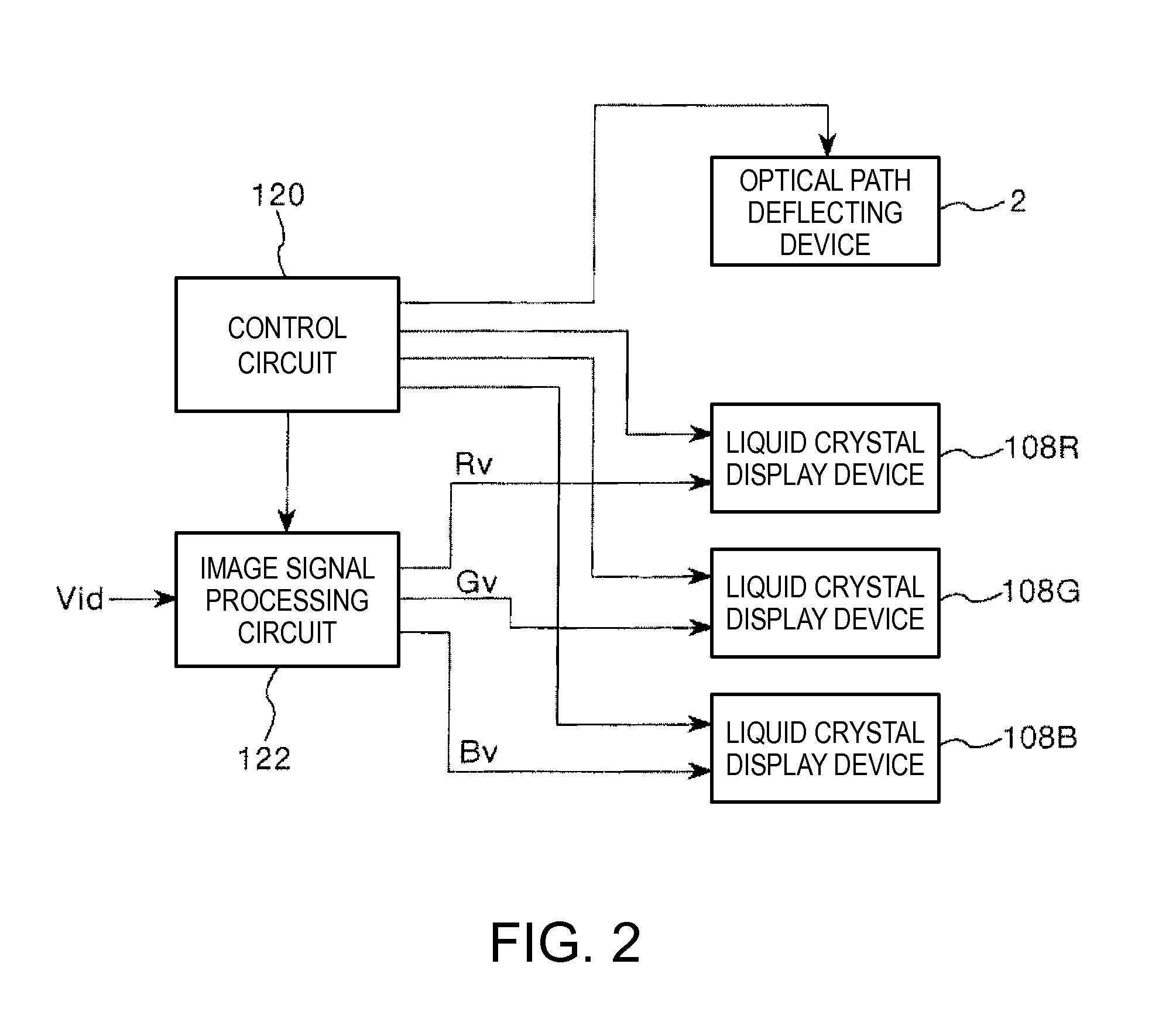
[0056]FIG. 1 shows the optical configuration of the projector using the image display apparatus according to the first embodiment of the invention. FIG. 2 is a block diagram showing the electrical configuration of the projector shown in FIG. 1. FIG. 3 is a perspective view showing the configuration of an optical path deflecting device shown in FIG. 1 (optical device according to the first embodiment of the invention). FIG. 4 is a plan view of the optical path deflecting device shown in FIG. 3. FIG. 5A is a cross-sectional view taken along the line A-A in FIG. 4. FIG. 5B is a cross-sectional view taken along the line B-B in FIG. 4. FIG. 6 is a cross-sectional view taken along the line C-C in FIG. 4. FIGS. 7A and 7B show how the op...
second embodiment
[0161]An optical path deflecting device using an optical device according to a second embodiment of the invention will next be described.
[0162]FIG. 11 is a cross-sectional view showing the configuration of the optical path deflecting device using the optical device according to the second embodiment of the invention. In FIG. 11, the same configurations as those in the embodiment described above have the same reference characters.
[0163]The second embodiment will be described below. The following description will be made primarily on items different from those in the first embodiment, and items that are the same as those in the first embodiment will not be described.
[0164]The second embodiment is the same as the first embodiment except that the restricting members are configured differently.
[0165]The optical path deflecting device 2 shown in FIG. 11 includes a restricting member 233. The restricting member 233 is so configured that it comes into contact with the optical member 202 whe...
third embodiment
[0168]An optical path deflecting device using an optical device according to a third embodiment of the invention will next be described.
[0169]FIG. 12 is a perspective view showing the configuration of the optical path deflecting device using the optical device according to the third embodiment of the invention. FIG. 13 is a plan view of the optical path deflecting device shown in FIG. 12. FIG. 14A is a cross-sectional view taken along the line D-D in FIG. 13. FIG. 14B is a cross-sectional view taken along the line E-E in FIG. 13. FIG. 15 shows how the optical path deflecting device shown in FIGS. 14A and 14B operates. In FIGS. 12 to 15, the same configurations as those in the embodiments described above have the same reference characters.
[0170]The optical path deflecting device 2 according to the present embodiment is the same as the optical path deflecting device 2 according to the first embodiment described above except that the drivers 220, the first restricting members 231, and ...
PUM
 Abstract
Description
Claims
Application Information
 - R&D
- Intellectual Property
- Life Sciences
- Materials
- Tech Scout
- Unparalleled Data Quality
- Higher Quality Content
- 60% Fewer Hallucinations
Browse by: Latest US Patents, China's latest patents, Technical Efficacy Thesaurus, Application Domain, Technology Topic, Popular Technical Reports.
© 2025 PatSnap. All rights reserved.Legal|Privacy policy|Modern Slavery Act Transparency Statement|Sitemap|About US| Contact US: help@patsnap.com


