RFID tag assemblies and process

Active Publication Date: 2015-10-01
HID TEXTILE SERVICES SARL
View PDF3 Cites 37 Cited by
  • Summary
  • Abstract
  • Description
  • Claims
  • Application Information

AI Technical Summary

Benefits of technology

[0019]In industrial laundries, wear and tear of linen or the like may be reduced by avoiding relatively sharp edges associated with a QFP

Problems solved by technology

However this often leads to cumbersome and inflexible solutions par

Method used


Image

  • RFID tag assemblies and process
  • RFID tag assemblies and process
  • RFID tag assemblies and process

Examples


Embodiment Construction

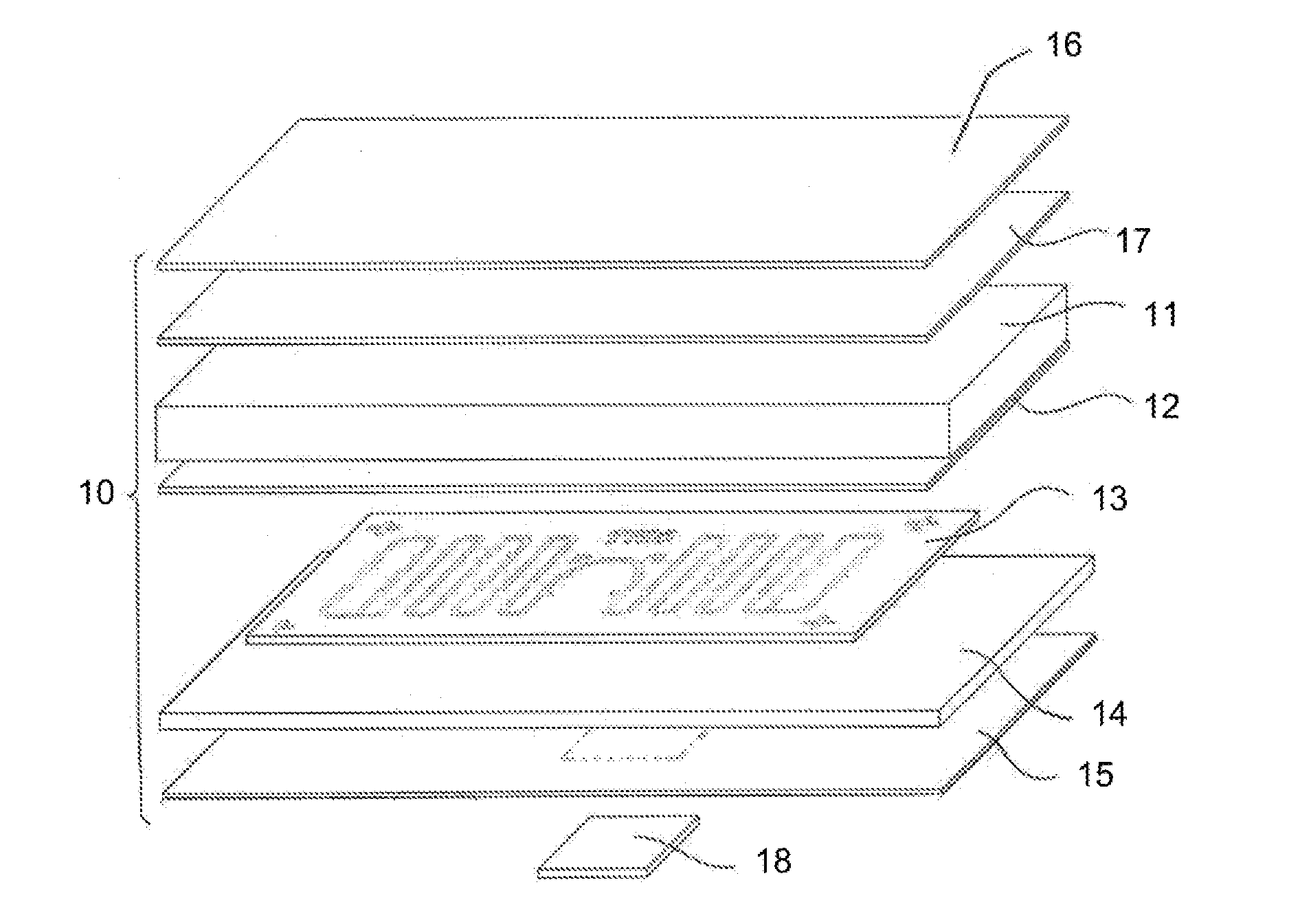
[0025]A tag assembly method is described below with reference to FIG. 1. FIG. 1 shows a thermo patch assembly 10 comprising at least the following layers:

1. a top woven polymeric sheet or synthetic layer 11;

2. an adhesive layer 12 for a secondary antenna layer;

3. a secondary antenna layer 13;

4. a heat activated adhesive layer 14; and

5. a relatively thin pressure sensitive adhesive (PSA) layer 15.

[0026]Top woven polymeric sheet or synthetic layer 11 may include a PI, PEN or PET substrate that is relatively resistant to high temperatures including temperatures that may be at least 200° C. or more. In one form the top layer 11 may include a PI layer that is 30 μm to 100 μm in thickness. Secondary antenna layer 13 may be provided on a woven (textile or fabric) or plastics (PEN) substrate. Secondary antenna layer 13 may include a 17 μm-35 μm thick etched copper layer to provide the radiating loop of the secondary antenna.

[0027]An optional over-layer 16 such as polycarbonate sheet or poly...


PUM

PropertyMeasurementUnit
Temperatureaaaaaaaaaa
Structureaaaaaaaaaa
Electrical inductanceaaaaaaaaaa

Abstract

A process is disclosed for attaching an RFID tag such as an AK module or QFP package to a flexible surface such as textile or fabric. The process comprises providing a heat fusible label including at least a first layer having a first adhesive layer, a substrate layer including a secondary antenna structure, a heat activated second adhesive layer and a pressure sensitive adhesive (PSA) layer for holding the RFID tag. The process further includes positioning the RFID tag on the PSA layer, pressing the tag against the PSA layer such that the PSA layer holds the tag against the heat fusible label at least temporarily, positioning the heat fusible label with the RFID tag on the flexible surface and applying heat and pressure to the heat fusible label to melt the heat activated layer and to fuse the label to the flexible surface.

Description

TECHNICAL FIELD[0001]The present invention relates to a tag assembly for attaching an RFID tag to a surface including a flexible surface such as textile or fabric and a process for producing an RFID tag assembly and / or label.CROSS REFERENCE TO RELATED APPLICATIONS[0002]The present invention is related to the following international patent applications assigned to the present applicant the disclosures of which are incorporated herein by cross reference: PCT / AU2010 / 000373—RFID TAG ASSEMBLY AND METHOD and PCT / AU2012 / 000305—RFID TAG ASSEMBLY AND LABEL PROCESS.BACKGROUND OF THE INVENTION[0003]Use of a generic RFID tag on a flexible surface such as textile or fabric typically involves stitching or bonding the tag directly to the fabric or enclosing it within a patch to provide an enclosure for the tag. However this often leads to cumbersome and inflexible solutions particularly with a clothing garment that may be uncomfortable to wear.[0004]In one prior art solution, a conductive thread i...

Claims


Application Information

Patent Timeline
IPC IPC(8): G06K19/077B32B37/18B32B37/12G06K19/02
CPCG06K19/0776G06K19/027B32B2519/02B32B37/1284B32B2037/1246B32B37/18Y10T156/10Y10T29/49018B32B37/12
Inventor MARTINELBAZ, DIDIERCOMBES, FRANCOIS
Owner HID TEXTILE SERVICES SARL
Why Eureka
Try Eureka