Systems and methods of switching coding technologies at a device

Active Publication Date: 2015-10-01
QUALCOMM INC
View PDF12 Cites 4 Cited by
  • Summary
  • Abstract
  • Description
  • Claims
  • Application Information

AI Technical Summary

Benefits of technology

The patent text describes a method for reducing frame boundary artifacts and energy mismatches when switching between different coding technologies. This is done by using a combination of MDCT and ACELP decoders, where the ACELP decoder decodes the first frame and generates "overlap" samples for the second frame. The MDCT decoder then uses these samples to perform a smoothing operation during decoding of the second frame, resulting in a smoother signal at the frame boundary. The technical effect of this method is that it improves the perceived quality of the audio signal when switching between different encoders or decoders in a device.

Problems solved by technology

The challenge is to retain high voice quality of the decoded speech while achieving the target compression factor.
At low bit rates (e.g., 4 kbps and below), time-domain coders may fail to retain high quality and robust performance due to the limited number of available bits.
Hence, despite improvements over time, many CELP coding systems operating at low bit rates suffer from perceptually significant distortion characterized as noise.
Although LP vocoders provide reasonable performance generally, they may introduce perceptually significant distortion, characterized as buzz.
The voice call quality may suffer due to various reasons, such as environmental noise (e.g., wind, street noise), limitations of the interfaces of the communication devices, signal processing by the communication devices, packet loss, bandwidth limitations, bit-rate limitations, etc.
However, in order to improve coding efficiency, the higher frequency portion of the signal (e.g., 6.4 kHz to 16 kHz, also called the “high band”) may not be fully encoded and transmitted.
When the wireless telephone switches from using a first encoding technology to encode an audio signal to using a second encoding technology to encode the audio signal, audible artifacts may be generated at frame boundaries of the audio signal due to the resetting of memory buffers within the encoders.
When switching between the MDCT encoder and the ACELP encoder, memory buffers used for BWE may be reset (e.g., populated with zeroes) and filter states may be reset, which may cause frame boundary artifacts and energy mismatches.

Method used


Image

  • Systems and methods of switching coding technologies at a device
  • Systems and methods of switching coding technologies at a device
  • Systems and methods of switching coding technologies at a device

Examples


Embodiment Construction

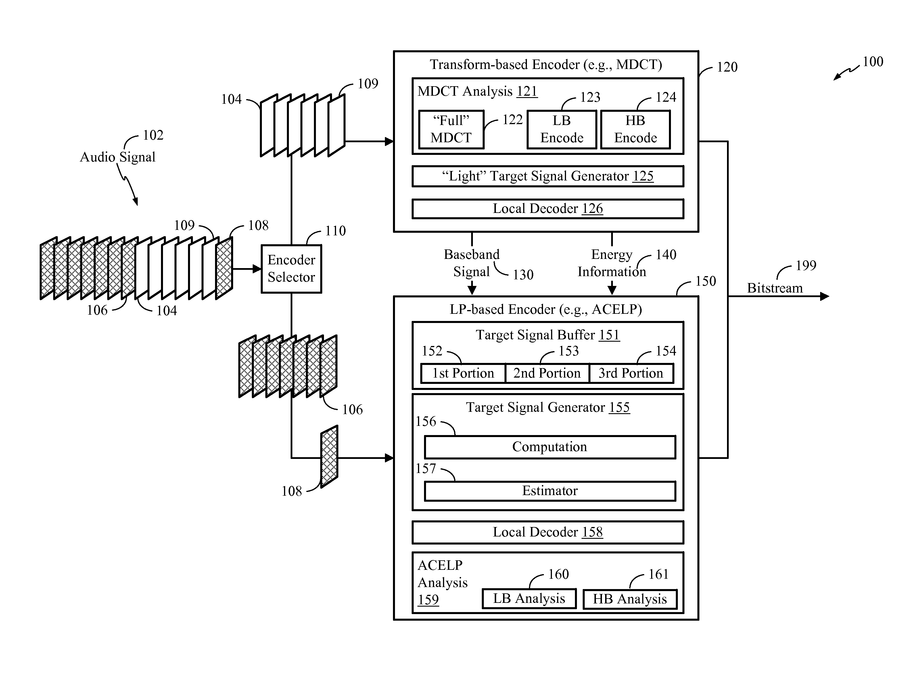
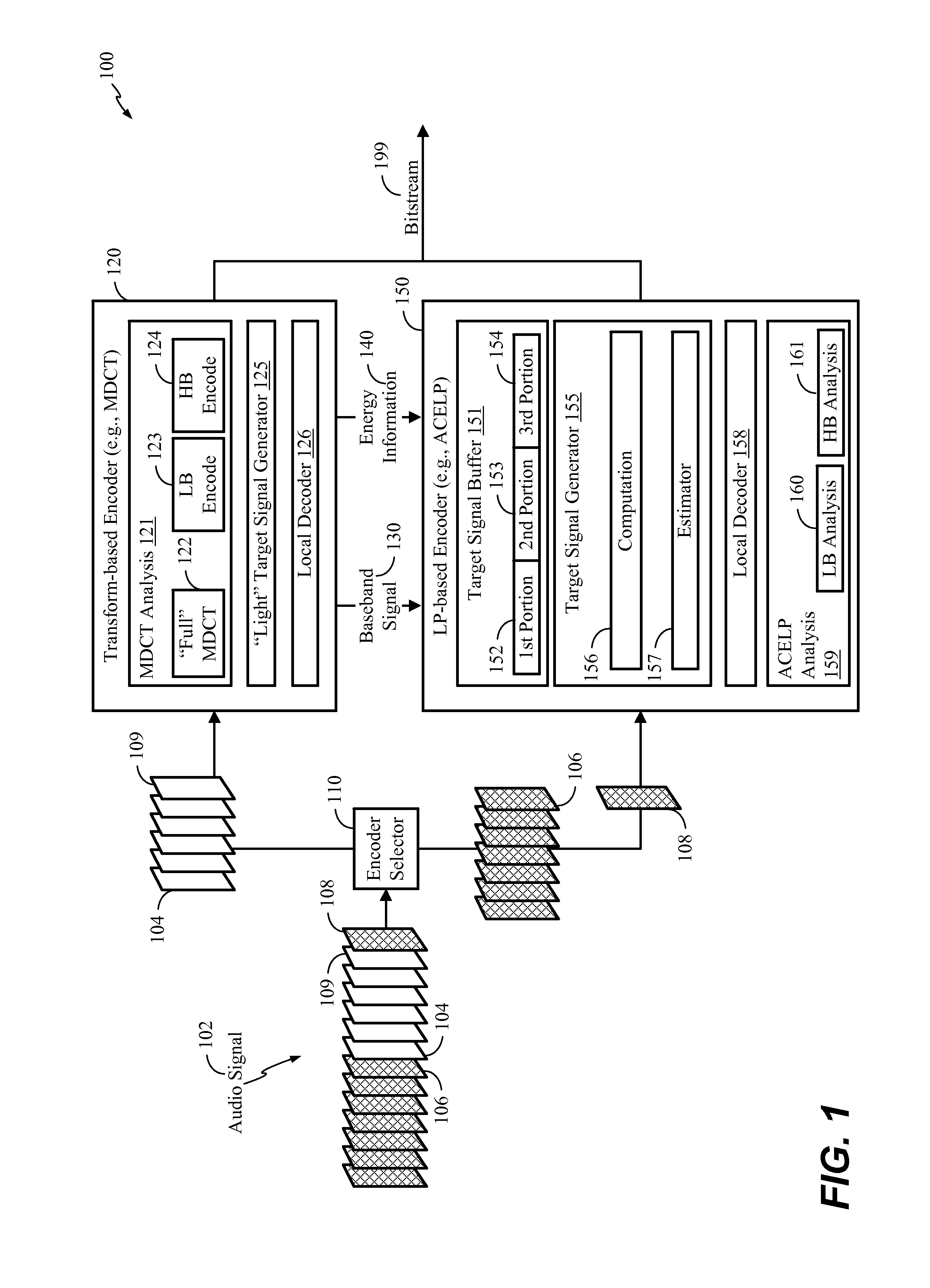
[0041]Referring to FIG. 1, a particular example of a system that is operable to switch encoders (e.g., encoding technologies) while reducing frame boundary artifacts and energy mismatches is depicted and generally designated 100. In an illustrative example, the system 100 is integrated into an electronic device, such as a wireless telephone, a tablet computer, etc. The system 100 includes an encoder selector 110, a transform-based encoder (e.g., an MDCT encoder 120), and an LP-based encoder (e.g., an ACELP encoder 150). In an alternate example, different types of encoding technologies may be implemented in the system 100.

[0042]In the following description, various functions performed by the system 100 of FIG. 1 are described as being performed by certain components or modules. However, this division of components and modules is for illustration only. In an alternate example, a function performed by a particular component or module may instead be divided amongst multiple components o...


PUM


Abstract

A particular method includes encoding a first frame of an audio signal using a first encoder. The method also includes generating, during encoding of the first frame, a baseband signal that includes content corresponding to a high band portion of the audio signal. The method further includes encoding a second frame of the audio signal using a second encoder, where encoding the second frame includes processing the baseband signal to generate high band parameters associated with the second frame.

Description

I. CLAIM OF PRIORITY[0001]The present application claims priority from U.S. Provisional Application No. 61 / 973,028, filed Mar. 31, 2014, which is entitled “SYSTEMS AND METHODS OF SWITCHING CODING TECHNOLOGIES AT A DEVICE,” the content of which is incorporated by reference in its entirety.II. FIELD[0002]The present disclosure is generally related to switching coding technologies at a device.III. DESCRIPTION OF RELATED ART[0003]Advances in technology have resulted in smaller and more powerful computing devices. For example, there currently exist a variety of portable personal computing devices, including wireless computing devices, such as portable wireless telephones, personal digital assistants (PDAs), and paging devices that are small, lightweight, and easily carried by users. More specifically, portable wireless telephones, such as cellular telephones and Internet Protocol (IP) telephones, can communicate voice and data packets over wireless networks. Further, many such wireless t...

Claims


Application Information

Patent Timeline
IPC IPC(8): G10L19/02G10L19/12
CPCG10L19/12G10L19/02G10L19/20G10L21/038
Inventor ATTI, VENKATRAMAN S.KRISHNAN, VENKATESH
Owner QUALCOMM INC
Why Eureka
Try Eureka