Low Latency Serial Data Encoding Scheme For Enhanced Burst Error Immunity and Long Term Reliability

Active Publication Date: 2015-10-01
HEWLETT-PACKARD ENTERPRISE DEV LP
View PDF0 Cites 9 Cited by
  • Summary
  • Abstract
  • Description
  • Claims
  • Application Information

AI Technical Summary

Benefits of technology

[0009]Therefore, to address the above disadvantages, various embodiments of the present invention provide a serial data encoding scheme that improves MTTFPA in the presence of decision feedback equalization (DFE) burst errors, without increasing latency. Estimated worst case correlated burst error and random error performance is plotted for three examples in FIG. 4, to compare the relative effectiveness of the approaches discussed above with the disclosed solution. Each ap

Problems solved by technology

The long term reliability of high speed serial interconnects is being challenged as transmission rates increase.
In particular, as bit rates increase, there is a corresponding increase in signal loss caused by the underlying physical media.
This signal loss is managed by increasing circuit complexity, using higher cost materials, and actively repeating the signal (or reducing the physical distance between nodes).
One cause of signal loss is due to the physical nature of digital transmission media.
If the voltage transition frequency (that is, the reciprocal of the transition time) represents even a modest fraction of the bit rate, this smearing may cause the sampled voltage to reach less than its optimum value at the sampling time, and in fact may cause the sampled voltage to indicate an incorrect bit value.
However, it is still possible to generate long runs of zeros or ones, occasionally causing strong voltage “smear” and incorrect bit decisions at the optimum sampling time as described above.
The DFE algorithm can cause burst errors, as now described.
A “burst error” occurs when an algorithm for which the determination of a given bit value as

Method used

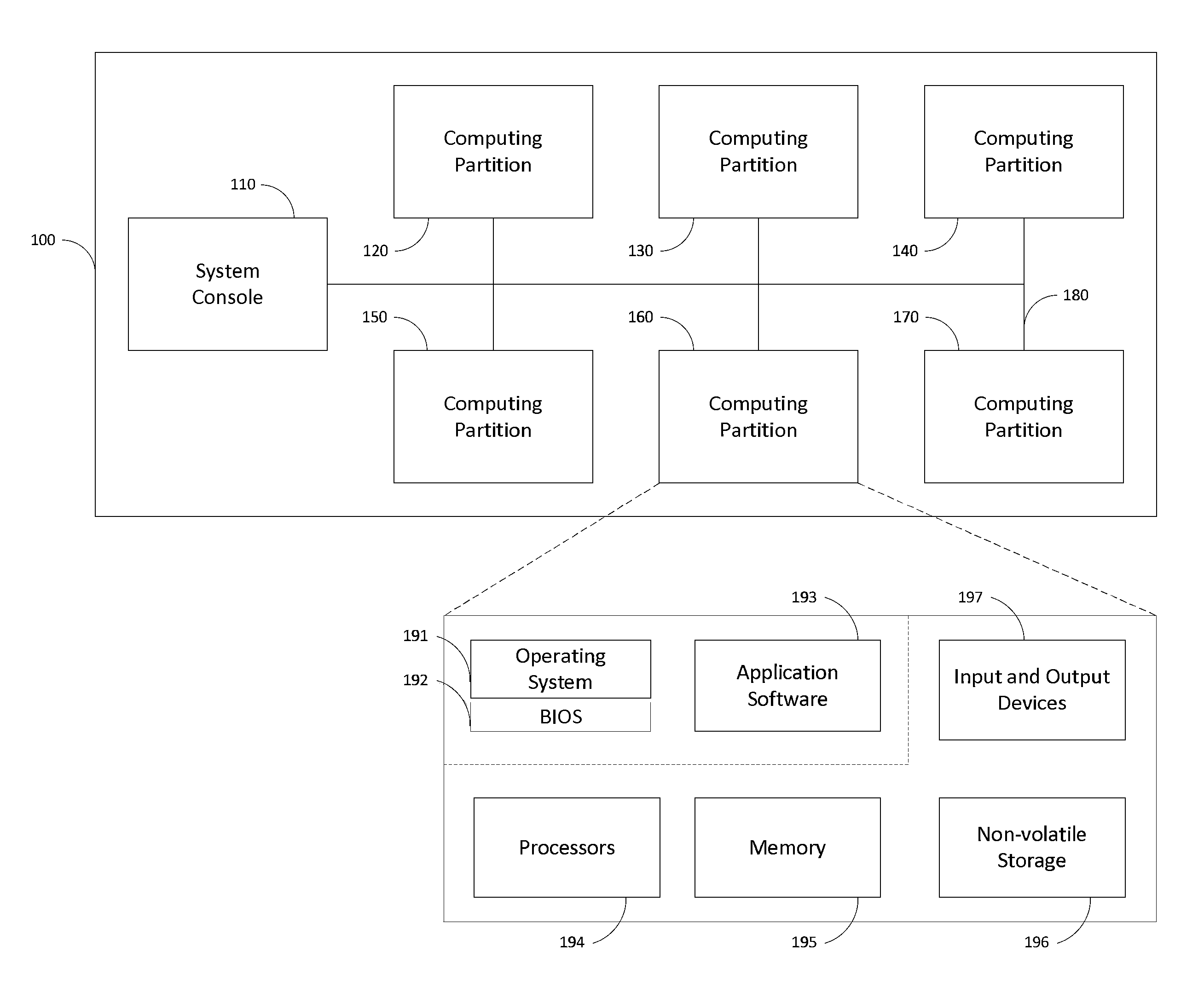
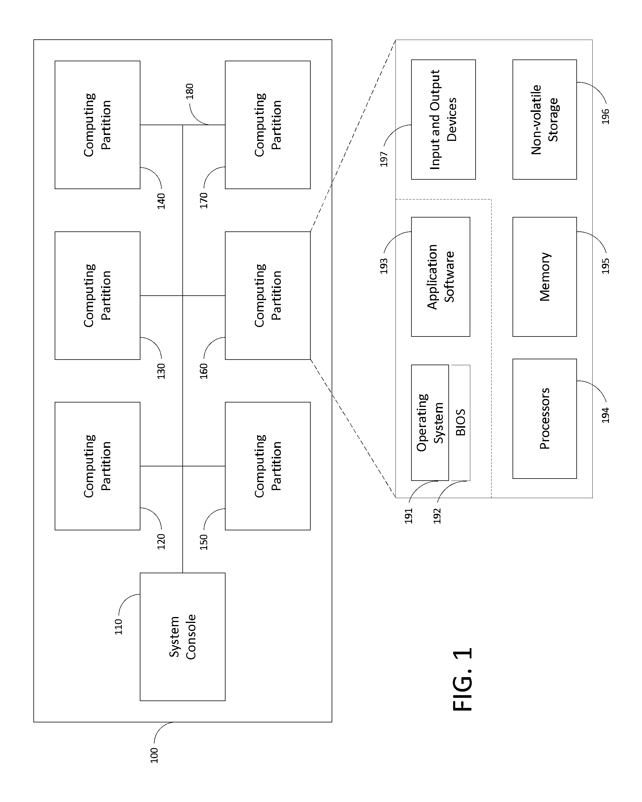
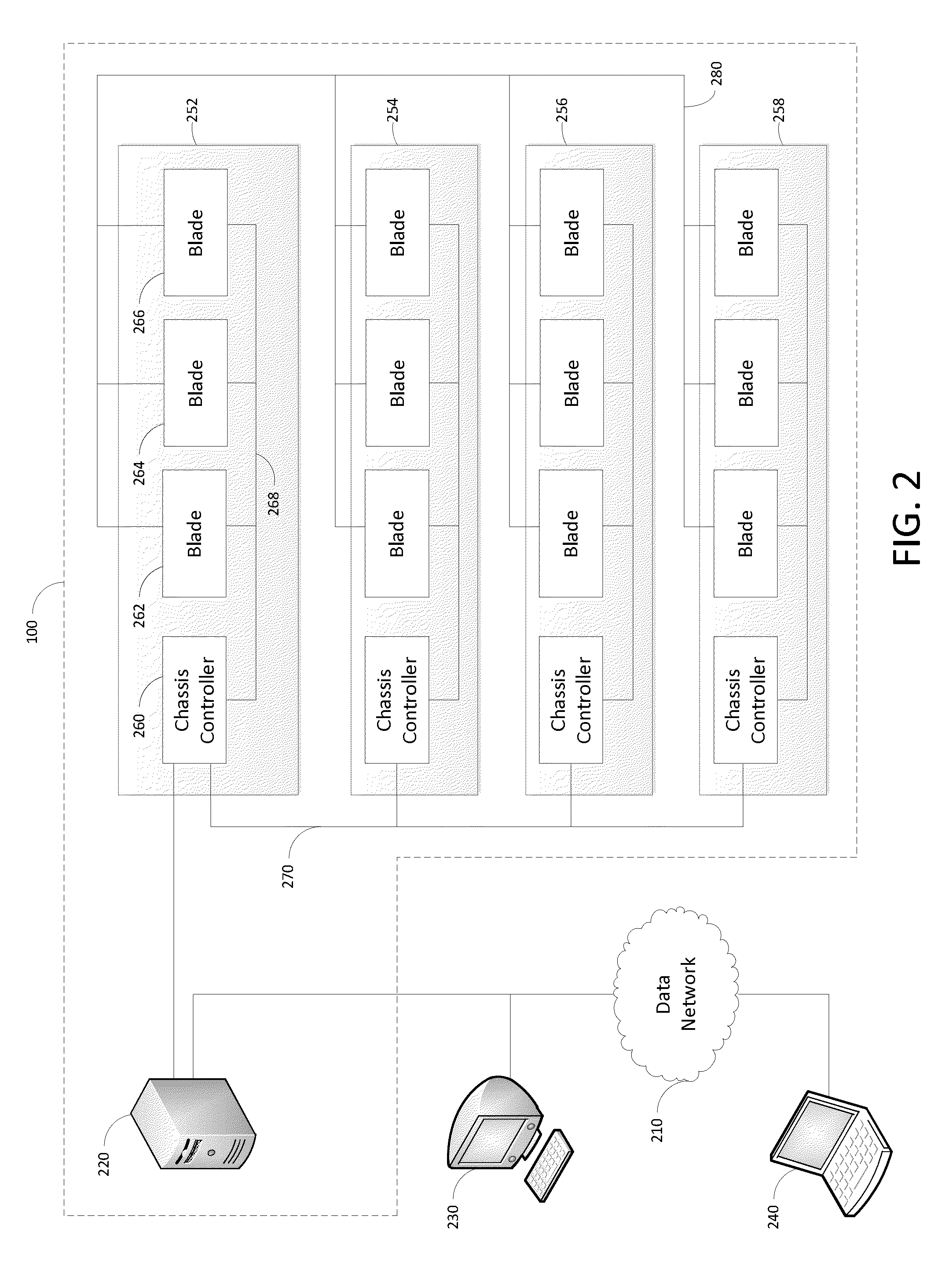

Image

  • Low Latency Serial Data Encoding Scheme For Enhanced Burst Error Immunity and Long Term Reliability
  • Low Latency Serial Data Encoding Scheme For Enhanced Burst Error Immunity and Long Term Reliability
  • Low Latency Serial Data Encoding Scheme For Enhanced Burst Error Immunity and Long Term Reliability

Examples


first embodiment

[0011]Therefore, in the invention, a computerized method of communicating a data packet using a communications link that has a plurality of communication lanes is provided. The method has five computerized processes. In the first process, the method provides the data packet with flow control information and error detection information, thereby forming a flow control unit. In the second process, the method chooses a transmission header from a plurality of headers as a function of a type of the data packet. The transmission header has a plurality of bits. In the third process, the method divides the flow control unit into equally sized payloads. The number of payloads is equal to the number of communication lanes, and each payload is associated with a respective communication lane. In the fourth process, the method inserts into each payload at an identical first location, a first bit of the chosen transmission header, and inserts, into each payload at an identical second location, a s...

second embodiment

[0024]FIG. 8 schematically shows an example of a modified block encoding according to the invention.

[0025]FIG. 9 schematically shows several examples of more general modifications that may be performed on block encodings in accordance with embodiments of the invention.


PUM


Abstract

A high performance computing system and method communicate data packets between computing nodes on a multi-lane communications link using a modified header bit encoding. Each data packet is provided with flow control information and error detection information, then divided into per-lane payloads. Sync header bits for each payload are added to the payloads in non-adjacent locations, thereby decreasing the probability that a single correlated burst error will invert both header bits. The encoded blocks that include the payload and the interspersed header bits are then simultaneously transmitted on the multiple lanes for reception, error detection, and reassembly by a receiving computing node.

Description

TECHNICAL FIELD[0001]The present invention relates to multiplex communications in a computer system, and more particularly to detecting and correcting burst errors in a multi-lane communications link.BACKGROUND ART[0002]High performance computing (HPC) systems include large, distributed systems having many computing nodes that communicate with each other to solve a shared computation. The connections between nodes are often formed from high speed serial interconnects that transmit bits of data (i.e., ones and zeroes) in parallel data lanes at a maximum speed, or bit rate. The long term reliability of high speed serial interconnects is being challenged as transmission rates increase. In particular, as bit rates increase, there is a corresponding increase in signal loss caused by the underlying physical media. This signal loss is managed by increasing circuit complexity, using higher cost materials, and actively repeating the signal (or reducing the physical distance between nodes). A...

Claims


Application Information

Patent Timeline
IPC IPC(8): H03M13/17H03M13/09
CPCH03M13/09H03M13/17H04L1/0083H04L1/0079H04L25/14H04L25/4908H04L1/0061H04L1/0057H03M13/11
Inventor SIKKINK, MARK RONALDDE RYCKERE, JOHN FRANCIS
Owner HEWLETT-PACKARD ENTERPRISE DEV LP
Why Eureka
Try Eureka