
Method and device for allocating resources

a resource allocation and resource technology, applied in the field of methods and devices for allocating resources, can solve the problems of reducing degrading voice service quality, and not maximizing channel capacity, so as to reduce the number of users of voice services, and ensure the quality of voice services

Active Publication Date: 2015-10-01
KT CORP
View PDF7 Cites 1 Cited by
  • Summary
  • Abstract
  • Description
  • Claims
  • Application Information

AI Technical Summary

Benefits of technology

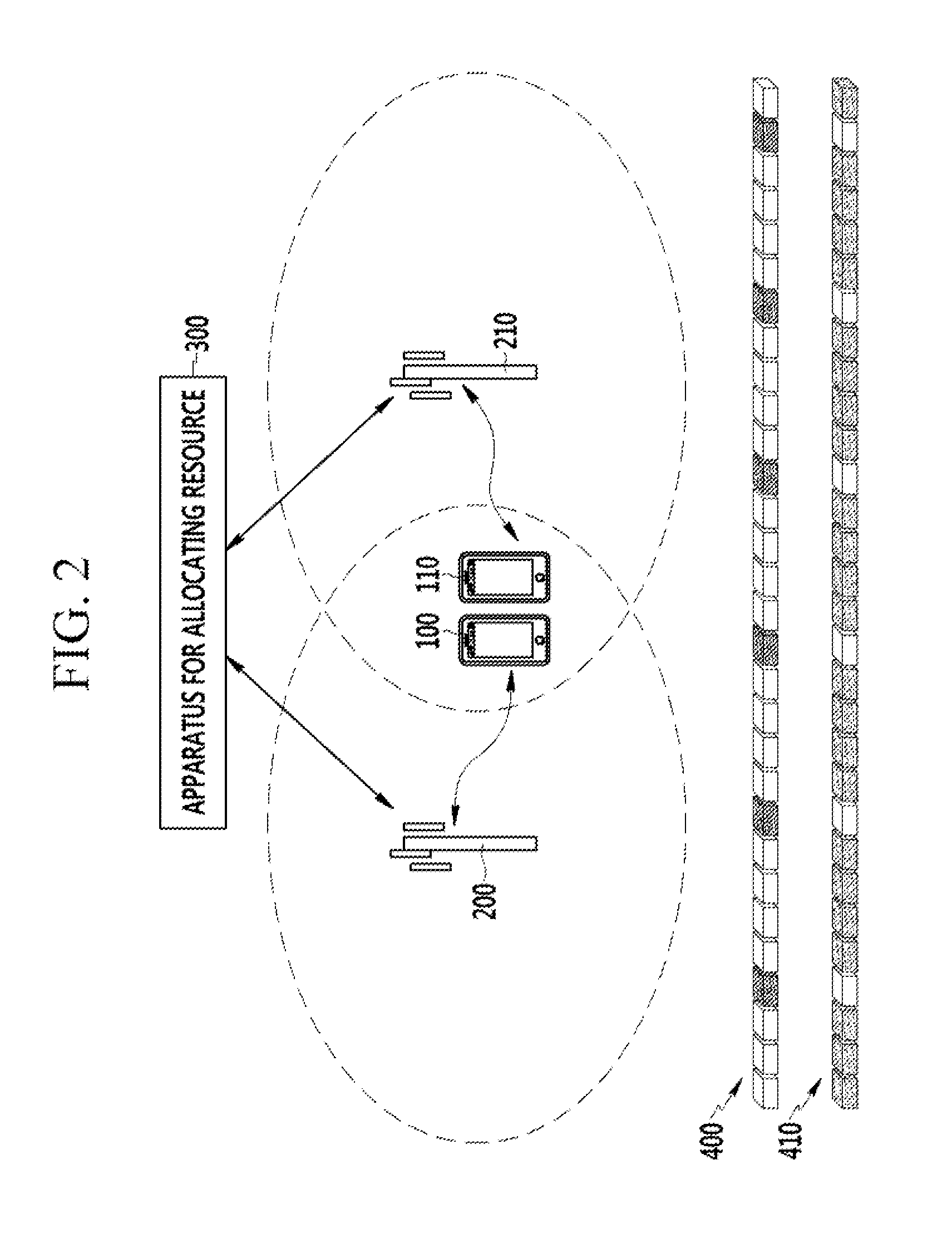
This patent aims to ensure good quality voice services and minimize data service degradation when both types of traffic are mixed. This is achieved by sharing inter-cell resource information, which allows for a more efficient use of resources. As a result, more users can be served.

Problems solved by technology

However, such a dynamic scheduling may saturate a control region if the dynamic scheduling allocates a plurality of small packets at a data region.
However, the semi-persistent scheduling may not maximize channel capacity.
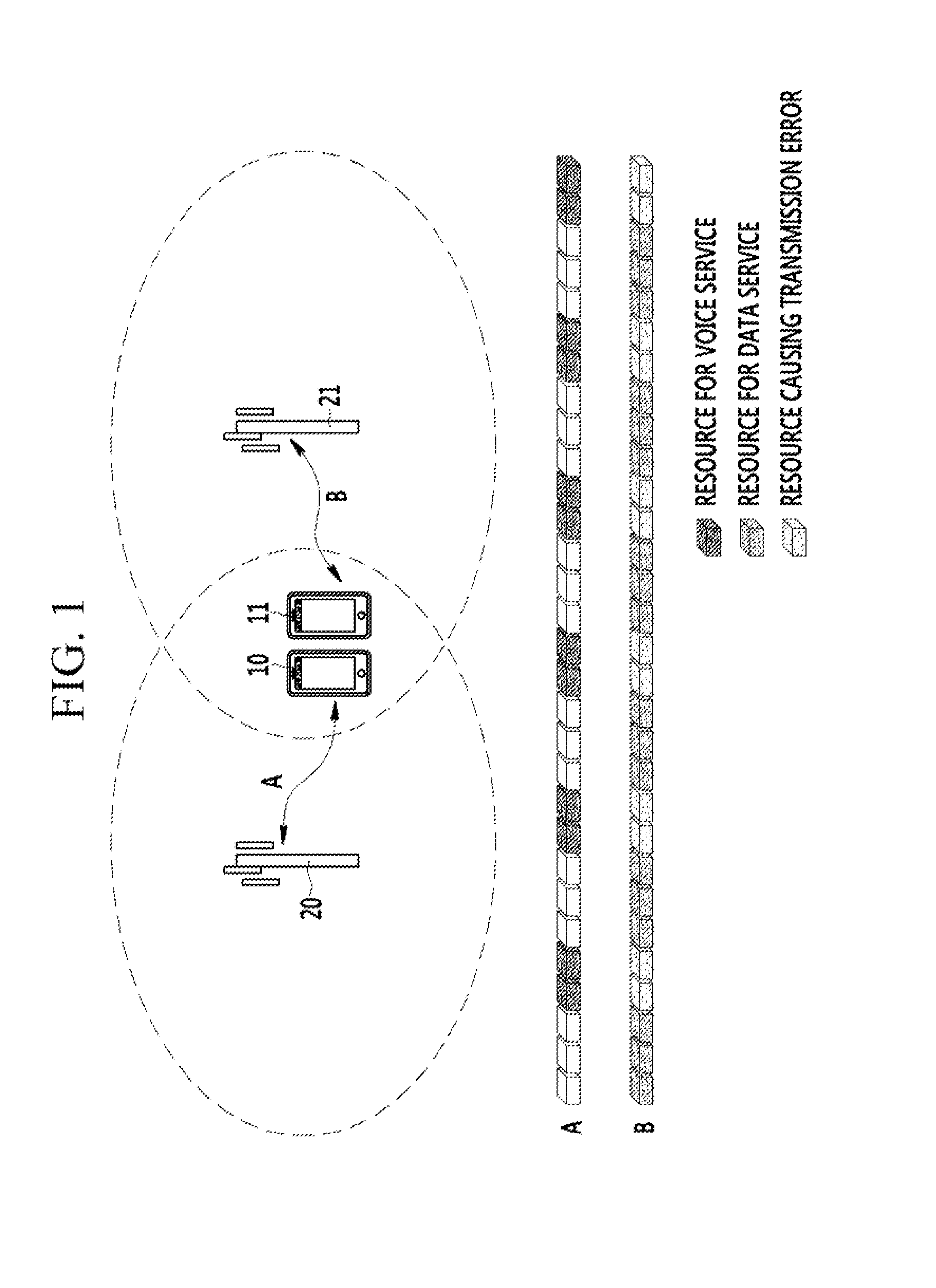
Therefore, such a typical resource allocation apparatus and method may degrade voice service quality due to inter-cell mutual interference.
In order to avoid such inter-cell interference problem, the typical resource allocation apparatus and method may allocate radio resources more than needed, which may reduce the number of users of a voice service.
In addition, the inter-cell interference may cause transmission error and degrade data service quality.

Method used


Image

  • Method and device for allocating resources
  • Method and device for allocating resources
  • Method and device for allocating resources

Examples


Embodiment Construction

[0031]In the following detailed description, only certain exemplary embodiments of the present invention have been shown and described, simply by way of illustration. As those skilled in the art would realize, the described embodiments may be modified in various different ways, all without departing from the spirit or scope of the present invention. Accordingly, the drawings and description are to be regarded as illustrative in nature and not restrictive. Like reference numerals designate like elements throughout the specification.

[0032]Throughout the specification, unless explicitly described to the contrary, the word “comprise” and variations such as “comprises” or “comprising” will be understood to imply the inclusion of stated elements but not the exclusion of any other elements.

[0033]In the present specification, a terminal may be referred to as a mobile station (MS), a mobile terminal (MT), a subscriber station (SS), a portable subscriber station (PSS), user equipment (UE), an...


PUM


Abstract

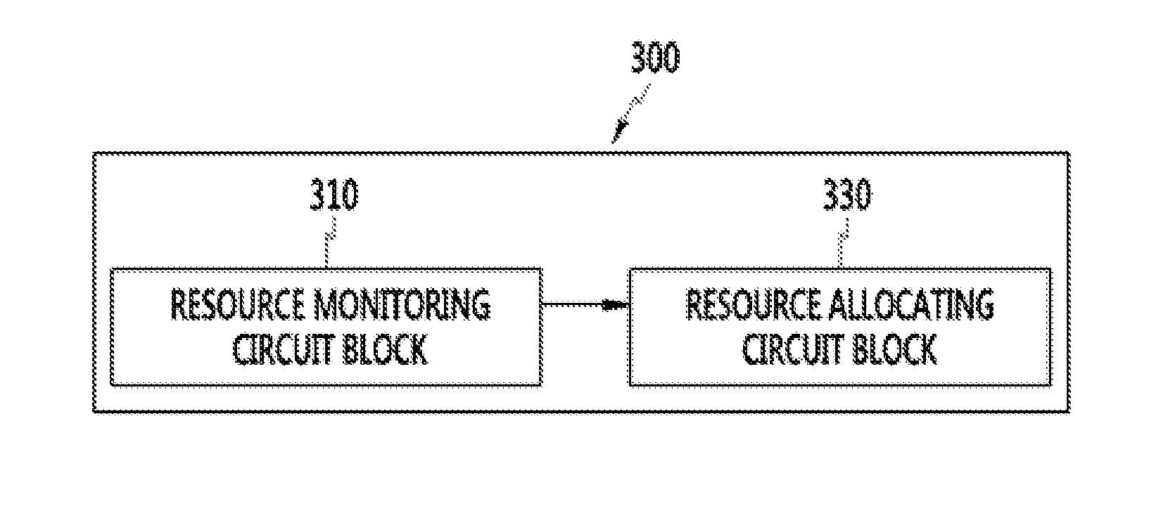
The present disclosure relates to resource allocation method and apparatus. The resource allocation method includes monitoring resource information of a plurality of base stations including a first base station and a second base station, receiving a resource allocation request from a first terminal that is located in a boundary region and connected to the first base station, and checking whether a second terminal using a voice service is located in the boundary region. When the second terminal is located in the boundary region, resources are allocated to the first terminal based on resources allocated to the second terminal. The boundary region is an overlapped region of cells of the first base station and the second base station.

Description

TECHNICAL FIELD[0001]The present disclosure relates to a method and an apparatus for allocating resources.BACKGROUND ART[0002]Long Term Evolution (LTE) may allocate resources to a terminal according to dynamic scheduling (DS) or semi-persistent scheduling. The dynamic scheduling is a resource allocation scheme that finds an optimal channel at each transmission time interval (TTI), in order to maximize channel capacity. However, such a dynamic scheduling may saturate a control region if the dynamic scheduling allocates a plurality of small packets at a data region.[0003]The semi-persistent scheduling does not allocate resources at each TTI. The semi-persistent scheduling uses a fixed resource allocation position and a fixed transmission scheme (e.g., modulation and coding scheme). The semi-persistent scheduling may reduce consumption of a Physical Downlink Control Channel (PDCCH). However, the semi-persistent scheduling may not maximize channel capacity.[0004]A typical resource alloc...

Claims


Application Information

Patent Timeline
Patent Type & Authority Applications(United States)
IPC IPC(8): H04W72/04H04L1/00H04W72/54
CPCH04W72/0446H04W88/02H04W88/08H04L1/0009H04L1/0003H04L5/0044H04L5/0073H04W28/24H04L5/0032H04L5/0069H04W72/54H04W72/04
Inventor LEE, KI-HOLEE, YONG-GYOOJI, YUNG-HA
Owner KT CORP
Learn More