Molding device for continuous casting with stirring unit

Active Publication Date: 2015-10-08
TAKAHASHI KENZO
View PDF0 Cites 5 Cited by
  • Summary
  • Abstract
  • Description
  • Claims
  • Application Information

AI Technical Summary

Benefits of technology

[0006]The invention has been made to solve the above-mentioned problems, and an object of the invention is to provide a molding device for continuous casting with a stirring unit that suppresses

Problems solved by technology

However, since the electromagnetic coil is disposed at the position close to high-temperature melt, not only the cooling of the electromagnetic coil and troublesome maintenance are needed but also large power consumption is naturally needed.
In addition, the

Method used


Image

  • Molding device for continuous casting with stirring unit
  • Molding device for continuous casting with stirring unit
  • Molding device for continuous casting with stirring unit

Examples


first embodiment

[0033]An embodiment of the invention will be described below with reference to the drawings. Meanwhile, a scale of a drawing is not necessarily the same in the respective drawings.

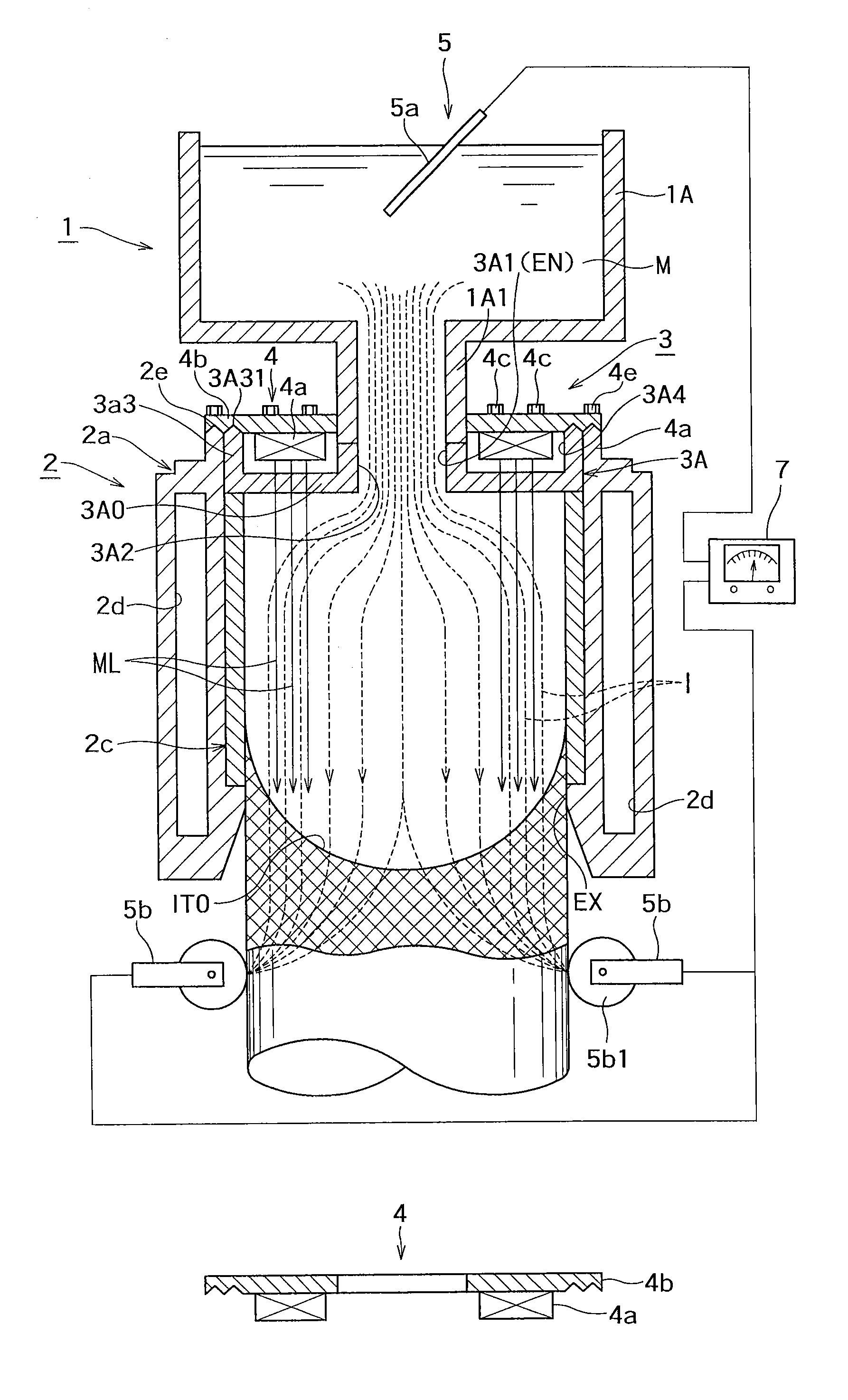
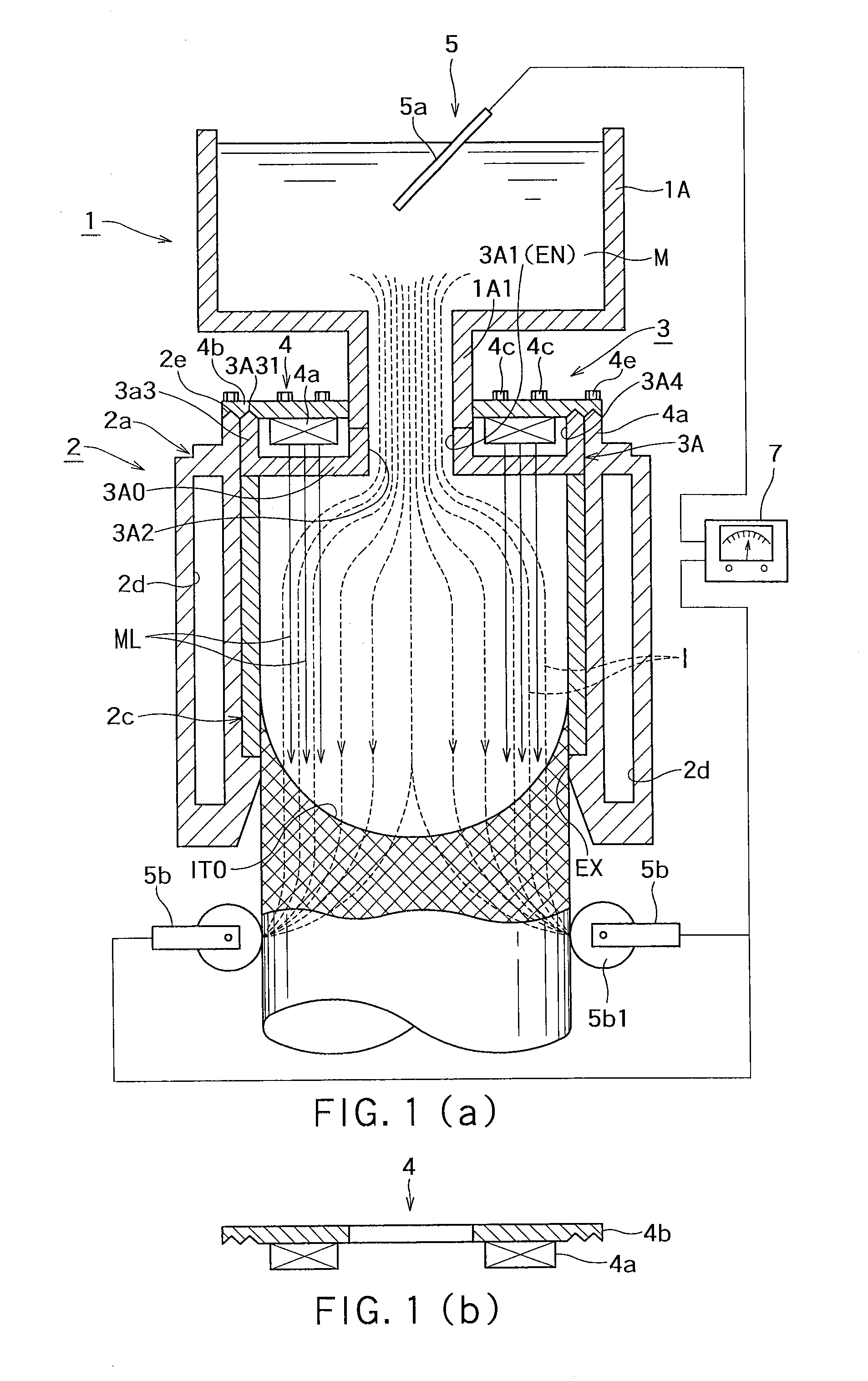
[0034]As understood from FIG. 1A, a device according to an embodiment of the invention includes a melt supply unit 1 that supplies melt M of non-ferrous metal of a conductor (conductive body), such as Al, Cu, Zn, or an alloy of at least two of them, or an Mg alloy, or melt M of other metal; a mold 2 that receives the melt from the melt supply unit 1; and a stirring unit 3 that stirs the melt M present in the mold 2.

[0035](1) Melt Supply Unit 1

[0036]The melt supply unit 1 includes a tundish (melt receiving box) 1A that receives melt M from a ladle (not illustrated) or the like. The melt M is stored in the tundish (melt receiving box) 1A, inclusion is removed from the melt, and the melt M is supplied to the mold 2 from a melt supply pipe portion 1A1, which is disposed below the tundish and is narrowed to hav...

second embodiment

[0069]FIG. 9 illustrates another embodiment of the invention. This embodiment is an embodiment in which a side magnet 45 is provided in the water jacket 2d. The side magnet 45 is provided so as to be adjustable in the water jacket 2d in a vertical direction. The side magnet 45 is illustrated in FIGS. 10(a) and 10(b). FIG. 10(a) is a plan view, and FIG. 10(b) is a longitudinal sectional view taken along line X(b)-X(b). As understood from FIGS. 10(a) and 10(b), the side magnet 45 is formed in a ring shape, the inside of the side magnet 45 is magnetized to a first pole (here, N pole), and the outside of the side magnet 45 is magnetized to a second pole (here, S pole). Alternatively, the inside and outside of the side magnet may be magnetized to the second pole and the first pole, respectively. Accordingly, lines MLs of magnetic force go toward the center. Further, the side magnet 45 may also be formed of a plurality of side magnet pieces having an arc-shaped cross-section.

[0070]In the ...


PUM

PropertyMeasurementUnit
Magnetic fieldaaaaaaaaaa
Magnetic forceaaaaaaaaaa

Abstract

A molding device includes a mold that forms a casting by cooling received melt, and a stirring unit that applies a magnetic field to the melt in the mold and allows a current to flow in the melt. The mold forms a vertical casting space that includes an inlet into which the melt flows and an outlet from which a product is taken. A transition plate is disposed at the mold space inlet. The melt can flow into the casting space from a hole in the transition plate. The stirring unit includes a magnetic field unit making lines of magnetic force vertically run into the casting space, and a first electrode at the inlet side and a second electrode at the outlet side that can flow current through the melt in the casting space, and generate an electromagnetic force by making the flowing current cross the lines of magnetic force.

Description

BACKGROUND OF THE INVENTION[0001]1. Field of the Invention[0002]The present invention relates to a molding device for continuous casting, which is equipped with a stirring unit, of continuous casting equipment that produces a billet, a slab or the like made of non-ferrous metal of a conductor (conductive body), such as Al, Cu, Zn, or an alloy of at least two of them, or an Mg alloy, or other metal.[0003]2. Background Art[0004]In the past, a melt stirring method to be described below has been employed in a mold for continuous casting. That is, for the improvement of the quality of a slab, a billet, or the like, in a process for solidifying the melt, that is, when the melt passes through the mold, a moving magnetic field, which is generated from the outside of the mold by an electromagnetic coil, is applied to the melt present in the mold so that stir occurs in the melt immediately before being solidified. A main object of this stir is to degas the melt and to uniformize the structure...

Claims


Application Information

Patent Timeline
IPC IPC(8): B22D11/115B22D11/00B22D11/124
CPCB22D11/115B22D11/124B22D11/004B22D11/003B22D11/001
Inventor TAKAHASHI, KENZO
Owner TAKAHASHI KENZO
Why Eureka
Try Eureka