Vehicle wrecker with improved controls

a technology of vehicle wrecker and control panel, which is applied in the direction of salvaging damaged vehicles, loading/unloading vehicle arrangments, transportation items, etc., can solve the problems of unfavorable access for the wrecker operator, and achieve the effect of facilitating longitudinal movemen

Active Publication Date: 2015-10-08
MILLER IND TOWING EQUIP INC
View PDF10 Cites 27 Cited by
  • Summary
  • Abstract
  • Description
  • Claims
  • Application Information

AI Technical Summary

Benefits of technology

[0012]In a preferred embodiment using a wrecker with a traveling boom, one or more traveler rollers are used to at least partially support the travel base assembly and to facilitate...

Problems solved by technology

However, vehicle wrecker users insist on redundant mechanical, manual back-up controls directly linked to the hydraulic valve, in the case of electrical failure.
The controls on a rotator or other heavy wrecker ar...

Method used


Image

  • Vehicle wrecker with improved controls
  • Vehicle wrecker with improved controls
  • Vehicle wrecker with improved controls

Examples


Embodiment Construction

[0025]Set forth below is a description of what are believed to be the preferred embodiments and / or best examples of the invention claimed. Future and present alternatives and modifications to this preferred embodiment are contemplated. Any alternatives or modifications which, make insubstantial changes in function, in purpose, in structure, or in result are intended to be covered by the claims of this patent.

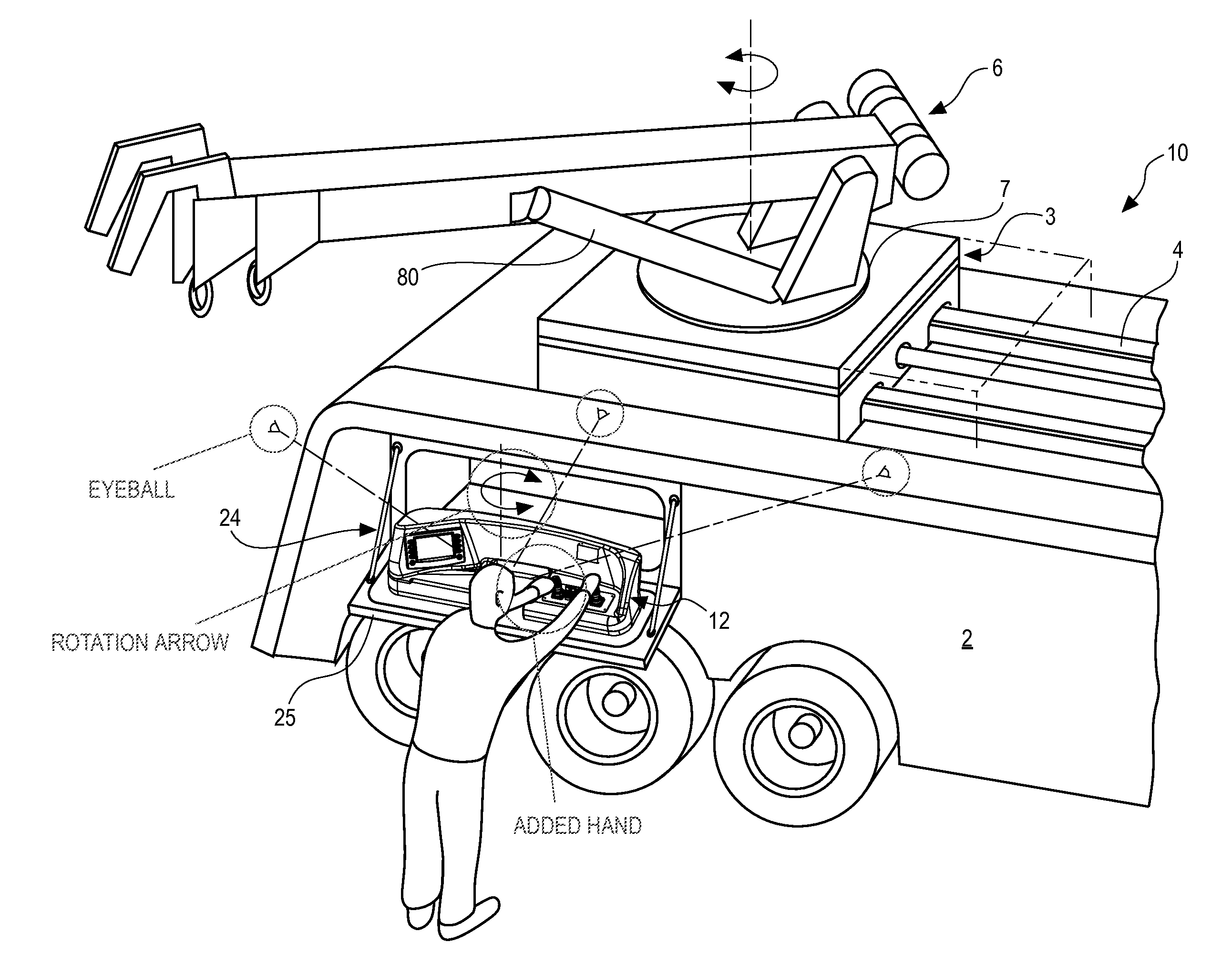
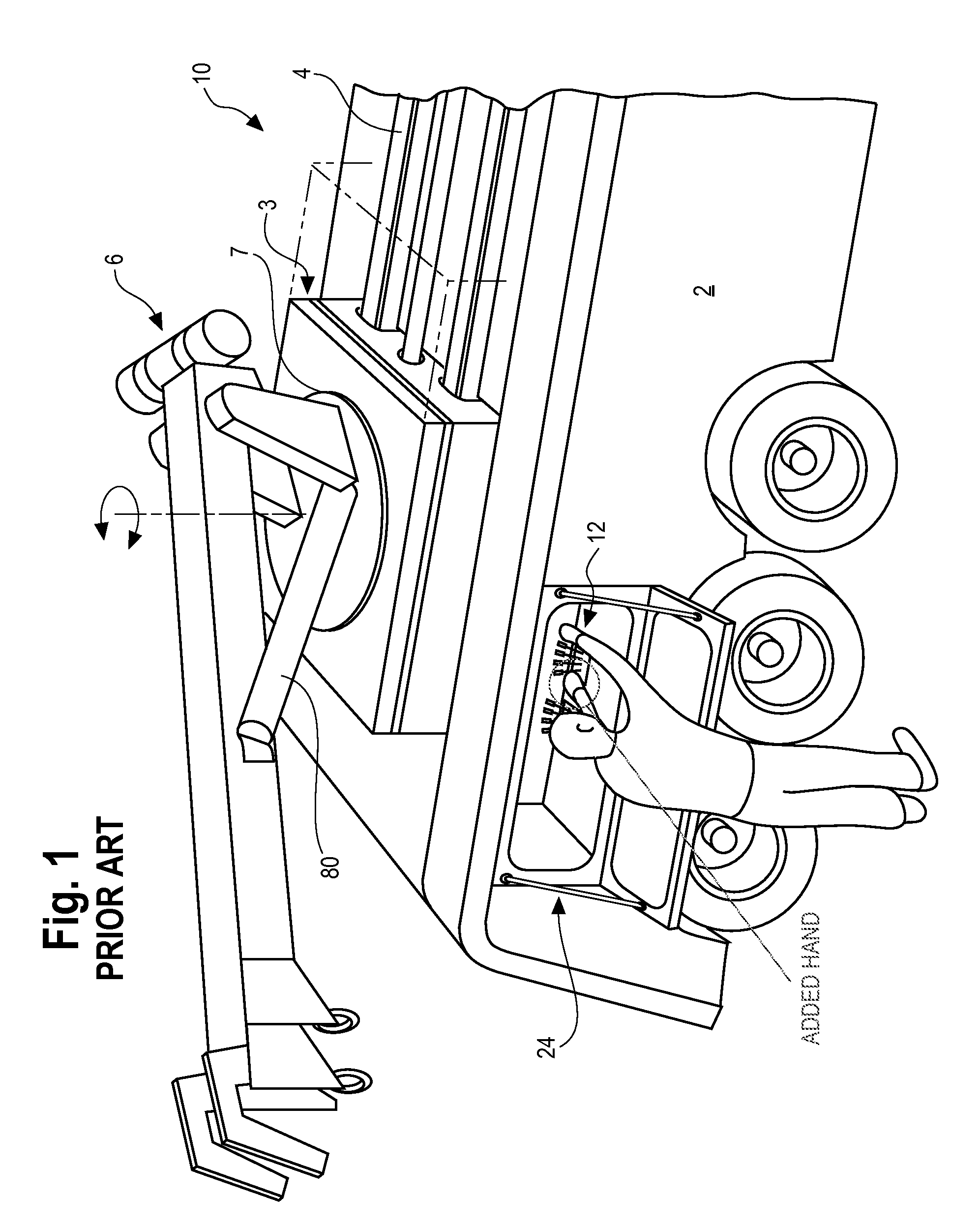
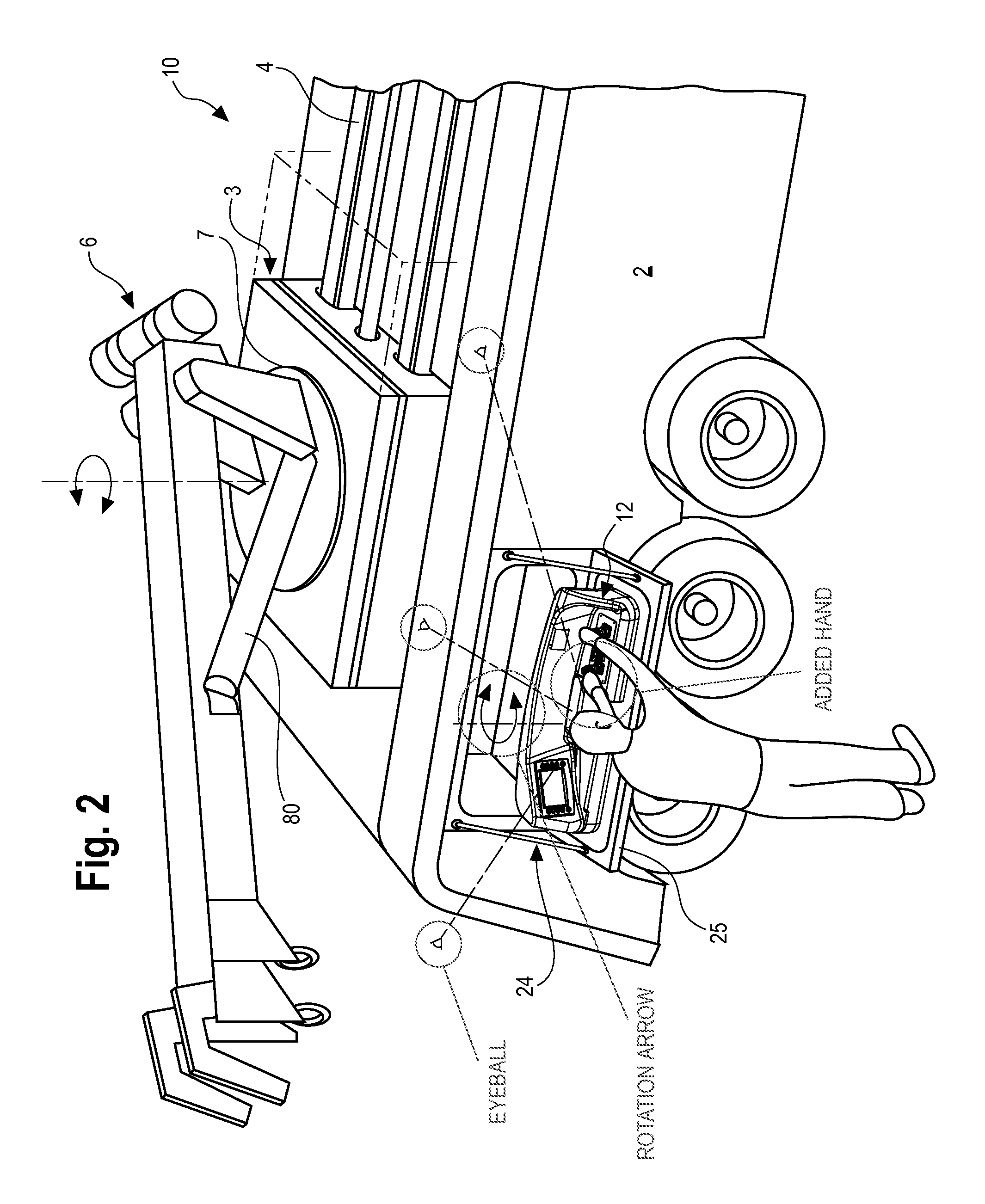
[0026]Referring now to prior art FIG. 1, rotating wrecker 10 with body 2 includes a wrecker assembly 8 with a telescoping boom 5 mounted on rotating bearing 7, which is in turned mounted on. travel base assembly 3. Travel base assembly 3 moves over travel tubes 4 along the longitudinal axis of the rotating wrecker, in the direction of the double-arrow. As disclosed in U.S. Ser. No. 13 / 565,100, between travel base assembly 3 and travel tubes 4, bearing pads, or alternatively one or more traveler rollers (i.e., rollers moveable about a load bearing member), may be located to facil...


PUM


Abstract

A wrecker-type recovery vehicle for recovering other, disabled vehicles, and a method for doing so, which may use a CAN Bus, and which may employ wrecker controls located a distance from a side surface of the vehicle exterior, Traveler rollers may be used to facilitate longitudinal movement of a travel base assembly supporting the boom, relative to the vehicle frame.

Description

BACKGROUND OF THE INVENTION[0001]Pending U.S. Ser. No. 13 / 565,100, titled “Traveler Roller,” filed Aug. 2, 2012, is hereby incorporated by reference in its entirety into this patent application.[0002]The present invention generally relates to vehicle recovery devices with masts and booms (“vehicle wreckers”), including those that can be rotated (“rotating wreckers”), as well as those which cannot be rotated, and whose supporting travel base can be moved along the longitudinal axis of the wrecker, to increase the reach of the boom. Such large vehicle wreckers (“heavy wreckers”) allow a large load to he lifted and then moved a given distance forward or rearward along the wrecker longitudinal axis.[0003]The hydraulic controls for vehicle wreckers are typically located on a control panel located on the sidewall of the unit. A controller module sends electrical signals through a wiring harness to actuate solenoids at the hydraulic control valve spools. Wireless remote control systems com...

Claims


Application Information

Patent Timeline
IPC IPC(8): B66C23/42B66C13/40B66C23/62
CPCB66C23/42B66C13/40B66C23/62B60P3/12B60P1/5433B66C13/18
Inventor MCCONNELL, RALPHBROWN, JOSEPH C.HAWKINS, JOHN L.MILLER, III, WILLIAM G.DYER, MARK
Owner MILLER IND TOWING EQUIP INC
Why Eureka
Try Eureka