Trapped vortex fuel injector and method for manufacture

a technology of fuel injector and vortex, which is applied in the direction of continuous combustion chamber, machine/engine, electron beam welding apparatus, etc., can solve the problems of increasing undesirable emissions, affecting the flow field of combustion gas, and affecting the production of liquid fuel,

Active Publication Date: 2015-10-08
GENERAL ELECTRIC CO
View PDF7 Cites 40 Cited by
  • Summary
  • Abstract
  • Description
  • Claims
  • Application Information

AI Technical Summary

Problems solved by technology

However, higher combustion gas temperatures may increase the disassociation rate of diatomic nitrogen, thereby increasing the production of undesirable emissions such as oxides of nitrogen (NOx) for a particular residence time in the combustor.
One challenge with injecting a fuel into the combustion gas flow field using existing LLI or axial fuel staging systems is that the momentum of the combustion gases generally inhibits adequate radial penetration of the liquid fuel into the combustion gas flow field.
As a result, local evaporation of the liquid fuel may occur along an inner wall of the liner at or near the fuel injection point, thereby potentially resulting in a high temperature zone and / or high thermal stresses.
In addition, achieving and sustaining combustion in a gas turbine combustor is difficult due to various factors such as but not limited to fuel content, fuel temperature, ambient air conditions, engine load and / or operating condition of the gas turbine.
These various factors may potentially create flow instabilities which may affect the NOx emissions levels generated by the combustor.
However, this approach exposes the fuel injectors to the hot combustion gases which may potentially impact the mechanical life of the component and may lead to fuel coke buildup.

Method used


Image

  • Trapped vortex fuel injector and method for manufacture
  • Trapped vortex fuel injector and method for manufacture
  • Trapped vortex fuel injector and method for manufacture

Examples


Embodiment Construction

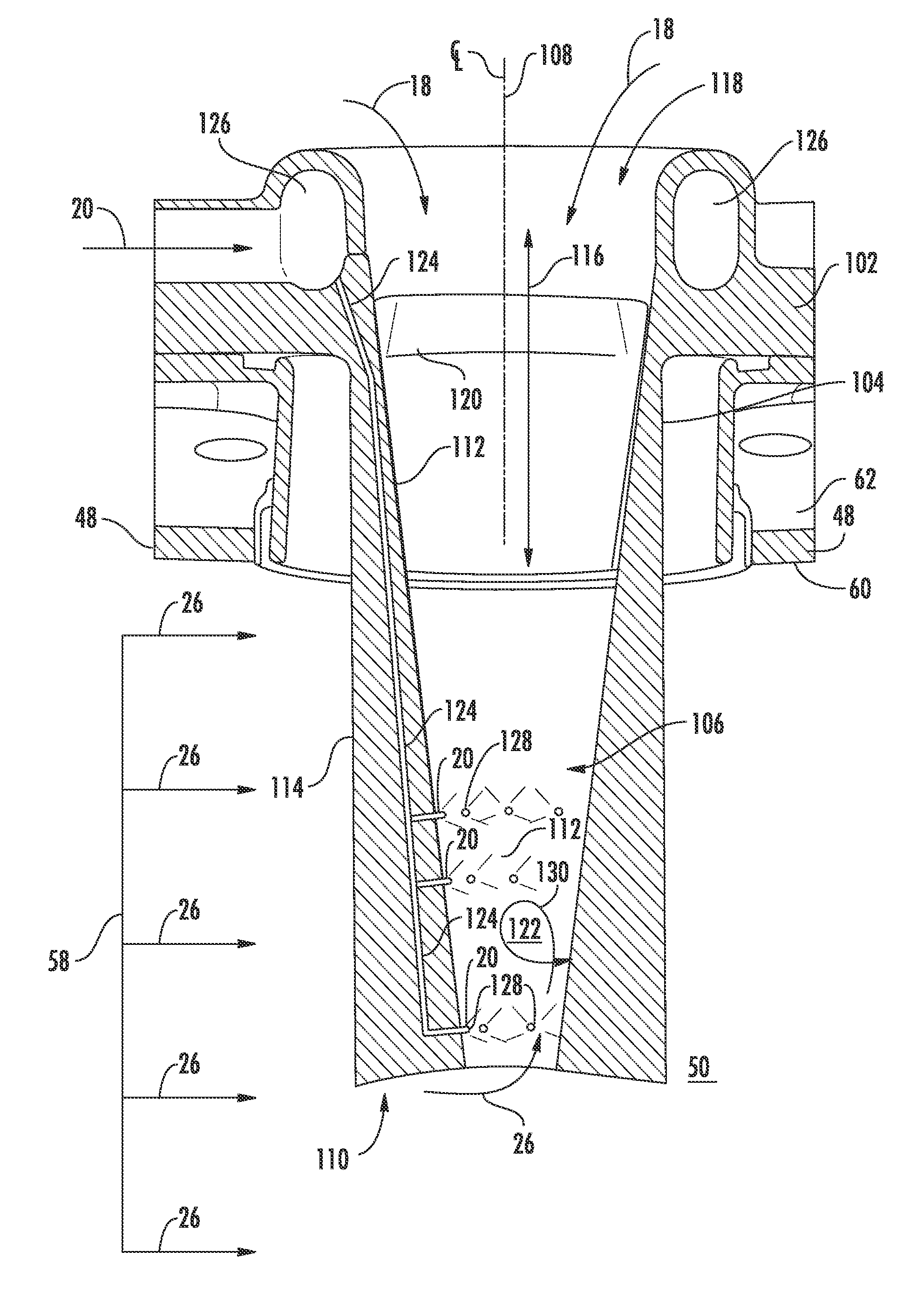
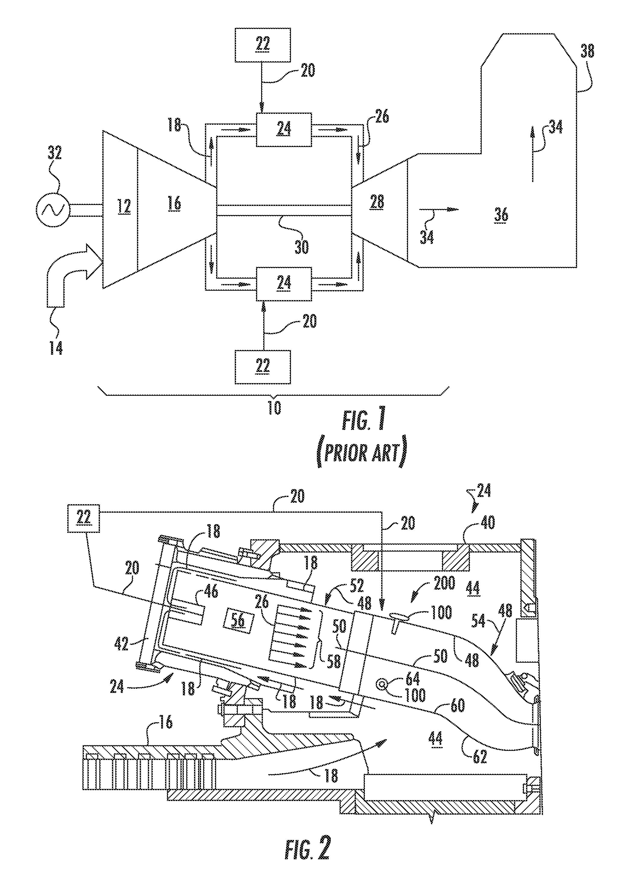
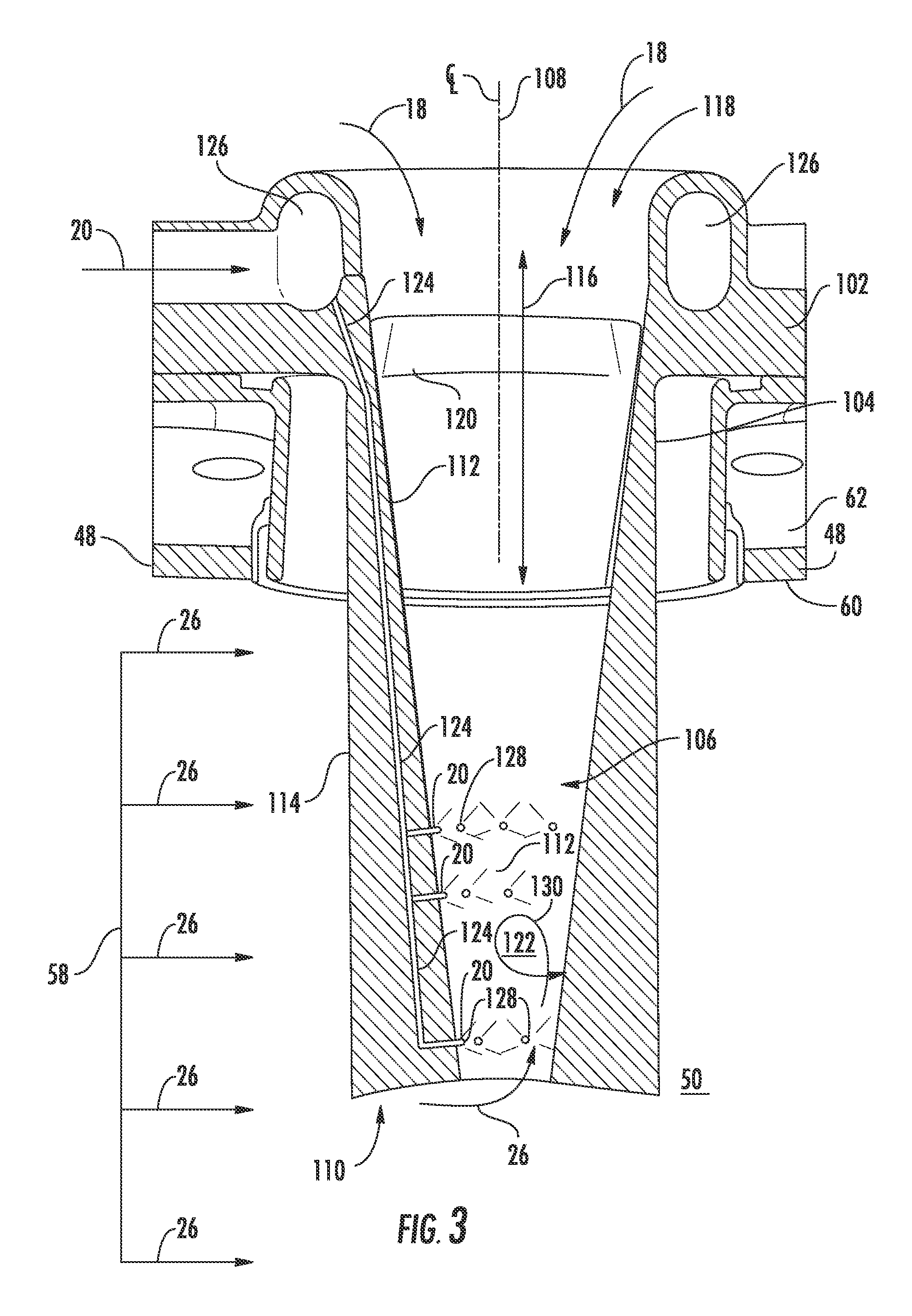
[0025]Reference will now be made in detail to present embodiments of the invention, one or more examples of which are illustrated in the accompanying drawings. The detailed description uses numerical and letter designations to refer to features in the drawings. Like or similar designations in the drawings and description have been used to refer to like or similar parts of the invention. As used herein, the terms “first”, “second”, and “third” may be used interchangeably to distinguish one component from another and are not intended to signify location or importance of the individual components. The terms “upstream” and “downstream” refer to the relative direction with respect to fluid flow in a fluid pathway. For example, “upstream” refers to the direction from which the fluid flows, and “downstream” refers to the direction to which the fluid flows. The term “radially” refers to the relative direction that is substantially perpendicular to an axial centerline of a particular compone...


PUM

PropertyMeasurementUnit
particle sizeaaaaaaaaaa

Abstract

A trapped vortex fuel injector includes a main body having an annular portion and a semi-annular portion coaxially aligned with the annular portion. The semi-annular portion extends downstream from the annular portion. An inner wall and an opposing outer wall of the main body extend between the annular and semi-annular portions. The annular portion at least partially defines a combustion air flow passage through the trapped vortex fuel injector. The semi-annular portion defines a trapped vortex pre-mix zone downstream from the combustion air flow passage. The main body further defines a fuel circuit that is fully circumscribed within the main body and that extends between the annular portion and the semi-annular portion. A plurality of fuel injection ports provide for fluid communication between the fuel circuit and the trapped vortex pre-mix zone. The main body may be fabricated using an additive manufacturing process.

Description

FIELD OF THE INVENTION[0001]The present invention generally involves a fuel injector for a combustor. More specifically, the invention relates to a trapped vortex fuel injector incorporated into a system for injecting a combustible mixture into a combustion gas flow field downstream from a primary combustion zone defined within the combustor and a method for manufacturing the trapped vortex fuel injector.BACKGROUND OF THE INVENTION[0002]A gas turbine generally includes a compressor section, a combustion section having a combustor and a turbine section. The compressor section progressively increases the pressure of the working fluid to supply a compressed working fluid to the combustion section. The compressed working fluid is routed through and / or around a fuel nozzle that extends axially within the combustor. A fuel is injected into the flow of the compressed working fluid to form a combustible mixture. The combustible mixture is burned within a combustion zone to generate combusti...

Claims


Application Information

Patent Timeline
Patent Type & Authority Applications(United States)
IPC IPC(8): F23R3/28B22F3/105B22F5/10F23R3/12B22F1/05
CPCF23R3/286F23R3/12F23R3/283B22F2304/10B22F5/10B33Y10/00B33Y80/00B22F3/1055F23R3/346F23R2900/00015F23R2900/00018F23R2900/03043F23R2900/03045B22F5/106C22C1/0433Y02P10/25B22F1/05B22F10/28B22F10/25B33Y50/02B23K26/342B23K26/702B22F2998/10B23K15/0086B23K15/0093B23K15/02B23K26/0006F02C7/14F05D2220/32F05D2230/22F05D2300/10
Inventor MELTON, PATRICK BENEDICT
Owner GENERAL ELECTRIC CO
Why Eureka
Try Eureka