Backlight Source, Liquid Crystal Display Panel and Liquid Crystal Display Device

Active Publication Date: 2015-10-08
BOE TECH GRP CO LTD +1
View PDF2 Cites 4 Cited by
  • Summary
  • Abstract
  • Description
  • Claims
  • Application Information

AI Technical Summary

Benefits of technology

The present invention provides a backlight source, liquid crystal display panel, and liquid crystal display device that overcome the drawbacks of existing liquid crystal smart phones or tablet PCs, such as high power consumption and poor endurance. The invention includes a light guide plate joined with at least two other light guide plates, and individually controlled light sources arranged outside the light guide plates. Each light guide plate can be lighted up individually, reducing power consumption and improving endurance. The invention also includes reflective surfaces at the joint of the light guide plates to prevent light leakage and improve brightness.

Problems solved by technology

As a result, the endurance of the smart phone fails to keep pace with the diversified and complex applications.

Method used


Image

  • Backlight Source, Liquid Crystal Display Panel and Liquid Crystal Display Device
  • Backlight Source, Liquid Crystal Display Panel and Liquid Crystal Display Device
  • Backlight Source, Liquid Crystal Display Panel and Liquid Crystal Display Device

Examples


first embodiment

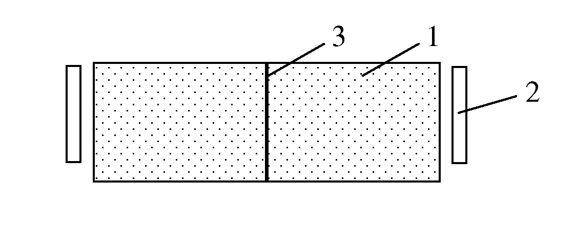
[0032]As shown in FIGS. 1 and 2, in this embodiment, the backlight source is of an edge-type, and the light guide plane is formed by joining two light guide plates 1. The light sources 2 are symmetrically arranged at two sides of the light guide plane, and oppose a joint of the two light guide plates 1. The light source 2 corresponding to the respective light guide plate 1 can be controlled individually by a control circuit. Two reflective surfaces 31 are provided at the joint of the two light guide plates 1, and oppose the light sources 2 arranged at two sides of the light guide plane. The reflective surfaces 31 may be directly formed on a joining surface of the two light guide plates, or a reflective plate 3 may be arranged at the joint of the two light guide plates 1 and the reflective surfaces 31 may be arranged at both sides of the reflective plate 3 that are in contact with the light guide plates 1. In other words, the reflective plate includes two reflective surfaces, which o...

second embodiment

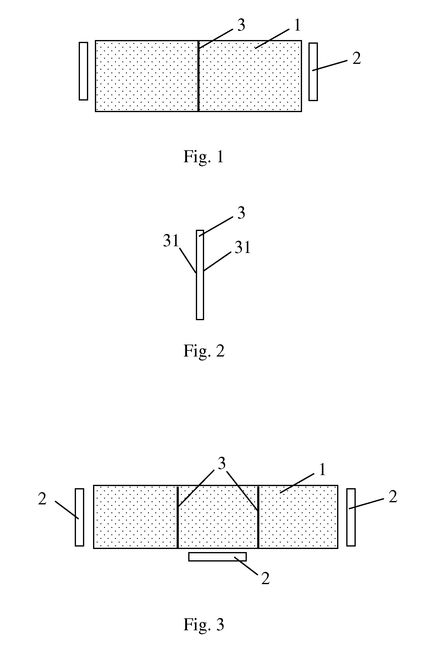
[0035]As shown in FIG. 3, in this embodiment, the backlight source is of an edge-type, and the light guide plane is formed by joining three light guide plates 1 end to end. The three light guide plates 1 are arranged in a row, and the light sources 2 are arranged outside the light guide plates 1 at both sides, and outside the middle light guide plate. The reflective surfaces 31 are provided at the joining surfaces of the light guide plates 1. The reflective surfaces 31 may be directly formed at the joining surfaces of two light guide plates, or the reflective plate 3 may be arranged at the joint of two light guide plates 1 and the reflective surfaces 31 may be arranged at both sides of the reflective plate 3 that are in contact with the light guide plates 1. The light sources 2 corresponding to the light guide plates at both sides are arranged outside the light guide plates and opposing the joining surfaces, while the light source corresponding to the middle light guide plate 1 is a...

third embodiment

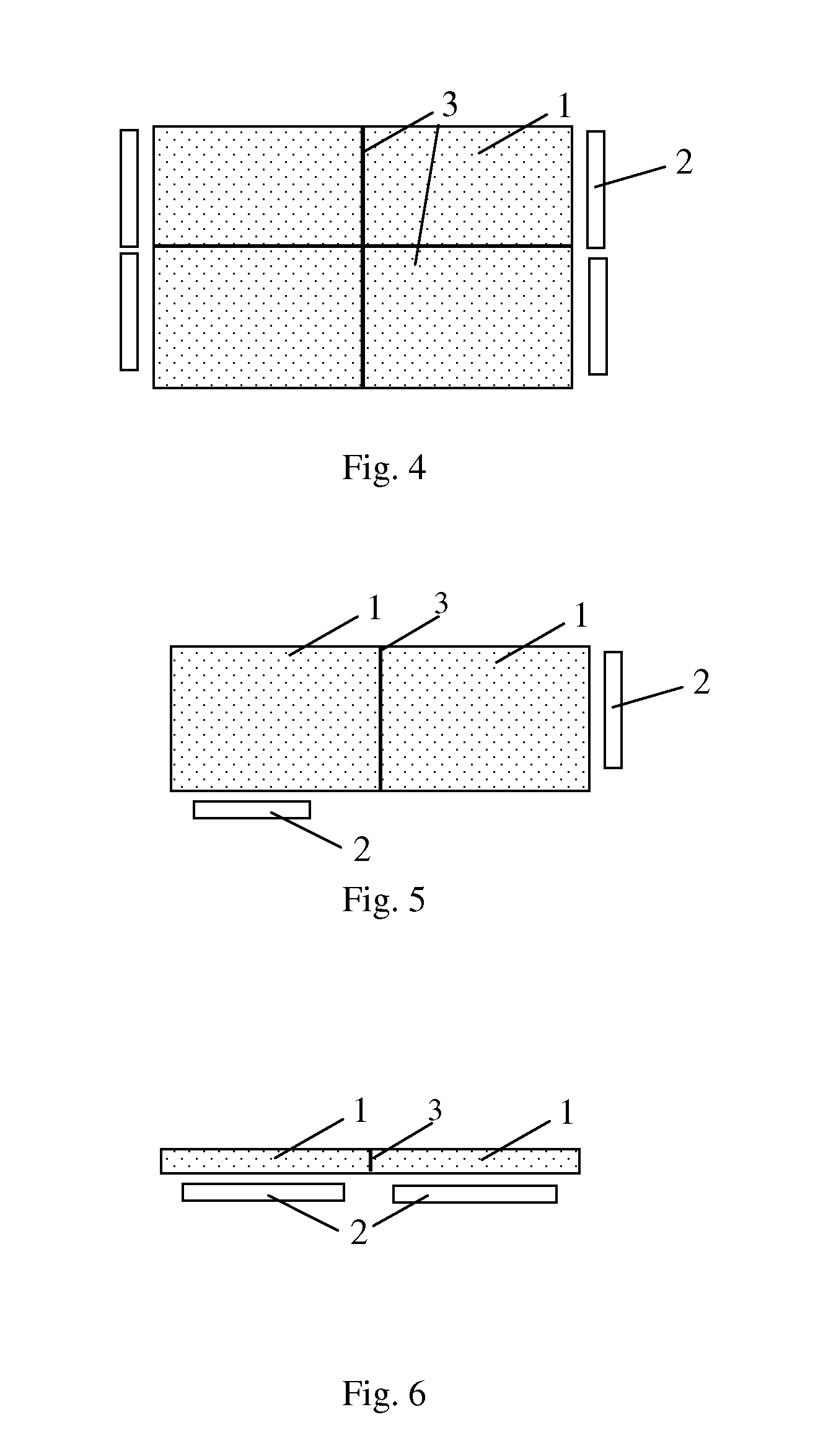
[0037]As shown in FIG. 4, in this embodiment, the backlight source is of an edge-type, and the light guide plane is formed by joining four light guide plates 1. The light sources 2 corresponding to the outside of the respective light guide plates 1 are symmetrically arranged at both sides of the light guide plane. The light source 2 corresponding to the respective light guide plate 1 can be controlled by the control circuit individually, and the reflective surfaces 31 are arranged at the joints of the four light guide plates 1. The reflective surfaces 31 may be directly formed on the joining surfaces of the four light guide plates, or the reflective plates 3 may be arranged at the joints of the four light guide plates 1 and the reflective surfaces may be arranged at both sides of the reflective plate 3 that are in contact with the light guide plates 1. When the light source corresponding to the light guide plate is lighted up, the region of the screen opposite thereto will not be li...


PUM


Abstract

The embodiment of the present invention relates to the field of display technology, and provides a backlight source, a liquid crystal display panel and a liquid crystal display device. The backlight source comprises at least two light guide plates and a light source corresponding to the respective light guide plate. The light guide plates are joined to form a light guide plane, and the light source is arranged at the periphery of the corresponding light guide plate and does not transmit light to the other light guide plate. The light source corresponding to the respective light guide plate can be controlled by a control circuit. According to the present invention, it is able to reduce the power consumption of the screen and the backlight source and improve the endurance of the backlight source.

Description

CROSS-REFERENCE TO RELATED APPLICATION[0001]The present application claims a priority of the Chinese patent application No. 201410137348.5 filed on Apr. 4, 2014, which is incorporated herein by reference in its entirety.FIELD OF THE INVENTION[0002]The embodiment of the present invention relates to the field of display technology, in particular to a backlight source, a liquid crystal display panel and a liquid crystal display device.DESCRIPTION OF THE PRIOR ART[0003]Each liquid crystal smart phone or computer includes a liquid crystal display panel, in which a backlight source is provided. Currently, a light guide plate of the backlight source is of an integral structure. Along with the popularization of the smart phone and the enhancement to application functions, more power is consumed by the existing liquid crystal display panel and backlight source. As a result, the endurance of the smart phone fails to keep pace with the diversified and complex applications. For the smart phone,...

Claims


Application Information

Patent Timeline
IPC IPC(8): F21V8/00G02F1/1335F21V23/00
CPCG02B6/0078G02B6/0068G02B6/0055G02B6/0073G02B6/0031G02B6/0071G02F1/133605G02F1/133603G02F1/133606
Inventor YANG, JIUXIABAI, FENGZHAO, YIMINGBAI, BINGSUN, XIAO
Owner BOE TECH GRP CO LTD
Why Eureka
Try Eureka