Method and apparatus for upper and lower tooth row three-dimensional simulation display

a three-dimensional simulation and display technology, applied in the field of three-dimensional simulation display of upper and lower tooth rows, can solve the problems of difficult to determine a “dynamic, difficult to produce occlusal surfaces, inaccurate relationship of occlusal position thus obtained with actual occlusal position, etc., to achieve the effect of promoting health and longevity of a nation

Inactive Publication Date: 2015-10-15
UNIVERSITY OF TOKUSHIMA +1
View PDF3 Cites 18 Cited by
  • Summary
  • Abstract
  • Description
  • Claims
  • Application Information

AI Technical Summary

Benefits of technology

[0067]One example of application of the method and apparatus according to the present invention is to provide information such as the jaw position and occlusion contact site at the time of manifestation of bruxism which has not been provided so far. Further, application can be made to an everyday dental clinical practice such as occlusal equilibration and a masticatory function test; it can be expected that, when a proper biting action cannot be performed, the spot to be scaled and the spot to be built up become quite obvious. Ultimately, dental treatment can be expected to be able to contribute more to health and longevity of a nation.

Problems solved by technology

However, since in these diagnostic examination methods, occluding paper, a special sheet or the like need to be inserted between upper and lower teeth, only “stationary” occlusion contact relations can mostly be determined, and it is difficult to determine a “dynamic” occlusion contact relation at a time of functioning, such as mastication or the like, and at a time of manifestation of bruxism that is considered as a developing factor or an aggravating factor of temporomandibular disorders.
However, in current systems, the technical work is digitized without precisely determining the occlusal position at present, and the occlusal position thus obtained has an inaccurate relationship with an actual occlusal position.
Further, since jaw movement data are not available, current systems have the problems such that proficient production of occlusal surfaces are difficult.

Method used


Image

  • Method and apparatus for upper and lower tooth row three-dimensional simulation display
  • Method and apparatus for upper and lower tooth row three-dimensional simulation display
  • Method and apparatus for upper and lower tooth row three-dimensional simulation display

Examples


Embodiment Construction

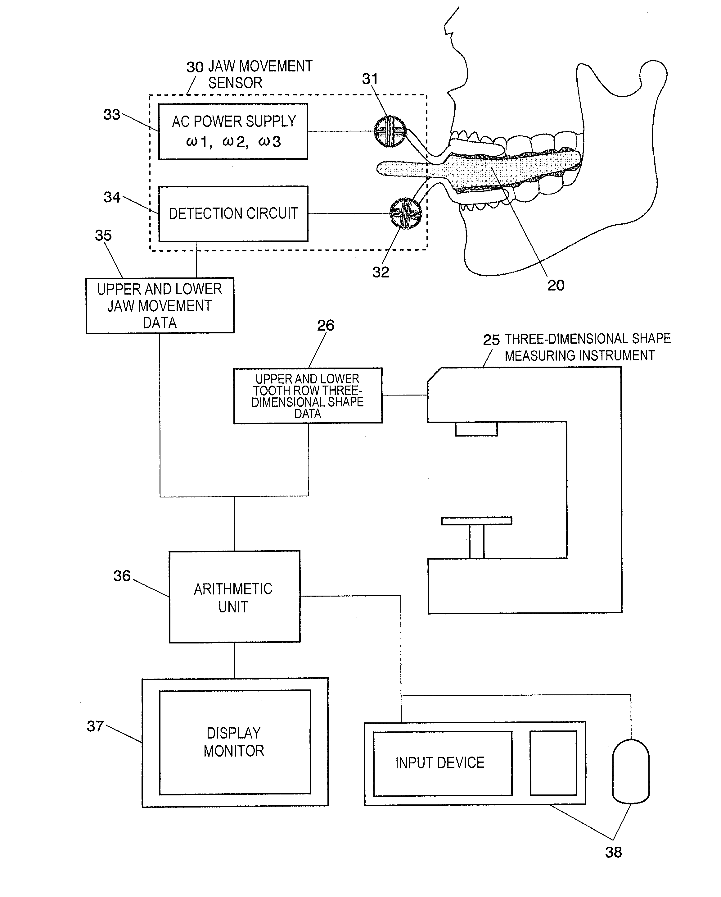
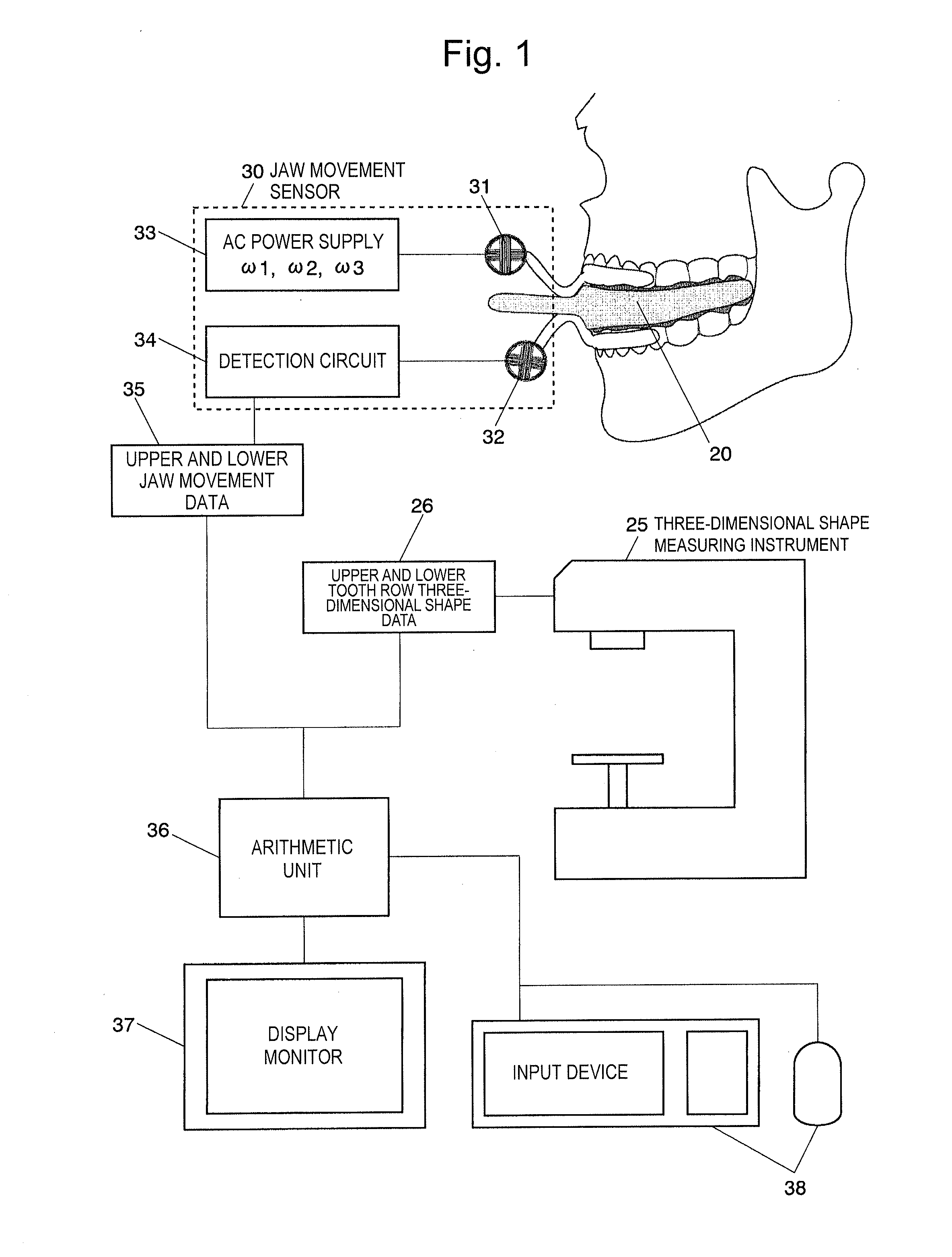
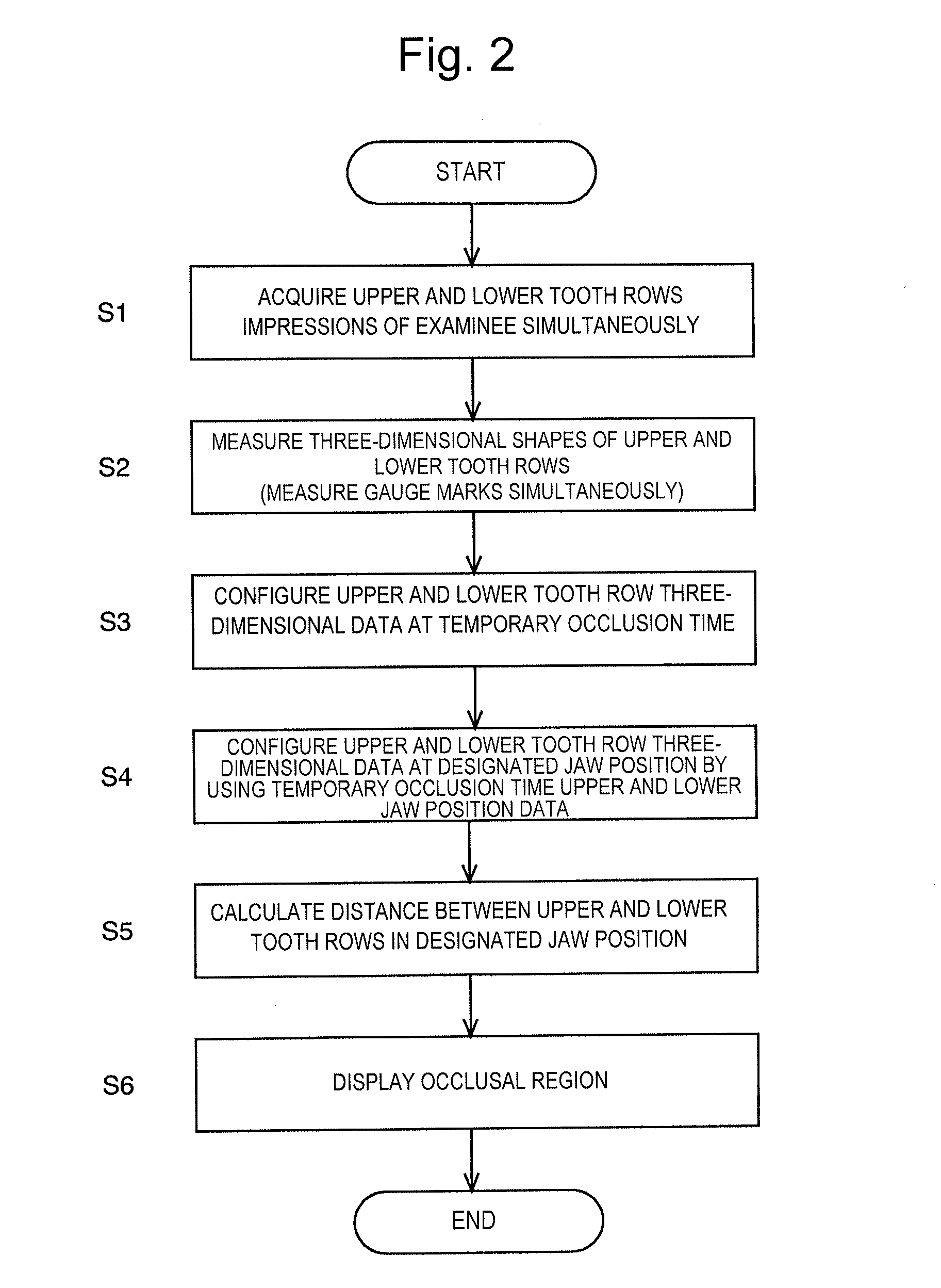
[0082]One embodiment of the present invention will be described based on a system schematic configuration diagram in FIG. 1 and a flowchart in FIG. 2.

[0083]As shown in FIG. 1, a system is constituted of a jaw movement sensor 30 for detecting a jaw position and jaw movement of an examinee, an impression plate 20 for simultaneously acquiring three-dimensional shapes of upper and lower tooth rows of the examinee, a three-dimensional shape measuring instrument 25 that generates three-dimensional shape data of the upper and lower tooth rows from the acquired impression plate 20, an arithmetic unit 36 that performs various arithmetic operations based on the acquired upper and lower jaw movement data 35 and the acquired upper and lower tooth row three dimensional shape data 26.

[0084]First, in order to measure three-dimensional shapes of the upper and lower tooth rows of an examinee, impressions of the upper and lower tooth rows are simultaneously acquired (step S1). More specifically, as s...


PUM


Abstract

A method and apparatus for performing simulation display of the three-dimensional shapes and occlusal contact region of the upper and lower tooth rows at a high speed. A jaw movement sensor fits an examinee, and data on jaw movement of the examinee is acquired. An impression plate including a rigid flat plate having a top surface and a bottom surface each coated with an impression material inserted between the examinee's upper and lower tooth rows to which the jaw movement sensor is fitted, and the examinee performs a temporary occlusion. Impressions left on the impression material and a gauge mark provided on the rigid flat plate are measured by using a three-dimensional measuring instrument, whereby the three-dimensional shape data of the upper and lower tooth rows and gauge mark are acquired. Simulation display of movement of the aforementioned is performed at a time of temporary occlusion and jaw movement data.

Description

TECHNICAL FIELD[0001]The present invention relates to a method and an apparatus for displaying three-dimensional simulation display of upper and lower tooth rows at a high speed. The present invention particularly relates to a method and an apparatus for measuring three-dimensional shapes of upper and lower tooth rows quickly, and determining occlusion of the upper and lower tooth rows at a high speed based on the three-dimensional shapes of the upper and lower tooth rows thus measured.BACKGROUND ART[0002]In dental examination and treatment, bite of upper and lower teeth (occlusion) very often has to be accurately recorded and diagnosed, but, in reality, dentists decide on courses of treatment depending on their experiences.[0003]As a diagnostic examination method of occlusion which is used in clinical dentistry, occluding paper is frequently used due to its convenience, and also black silicone, wax or the like for diagnostic examination of occlusion are sometimes used. Recently, oc...

Claims


Application Information

Patent Timeline
Patent Type & Authority Applications(United States)
IPC IPC(8): A61C19/05A61C9/00A61B5/107A61B5/00A61B5/11
CPCA61C19/05A61B5/4547A61B5/1111A61B5/1077A61B2560/0214A61C9/0006A61B5/7278A61B5/7246A61B5/7445A61B5/11A61B5/682A61C19/045
Inventor SHIGEMOTO, SHUJISATSUMA, TOYOKONOGUCHI, NAOTOSUZUKI, YOSHITAKAISHIKAWA, TERUAKIOKURA, KAZUO
Owner UNIVERSITY OF TOKUSHIMA
Why Eureka
Try Eureka