Corona discharge device and air-conditioning apparatus
- Summary
- Abstract
- Description
- Claims
- Application Information
AI Technical Summary
Benefits of technology
Problems solved by technology
Method used
Image
Examples
embodiment 1
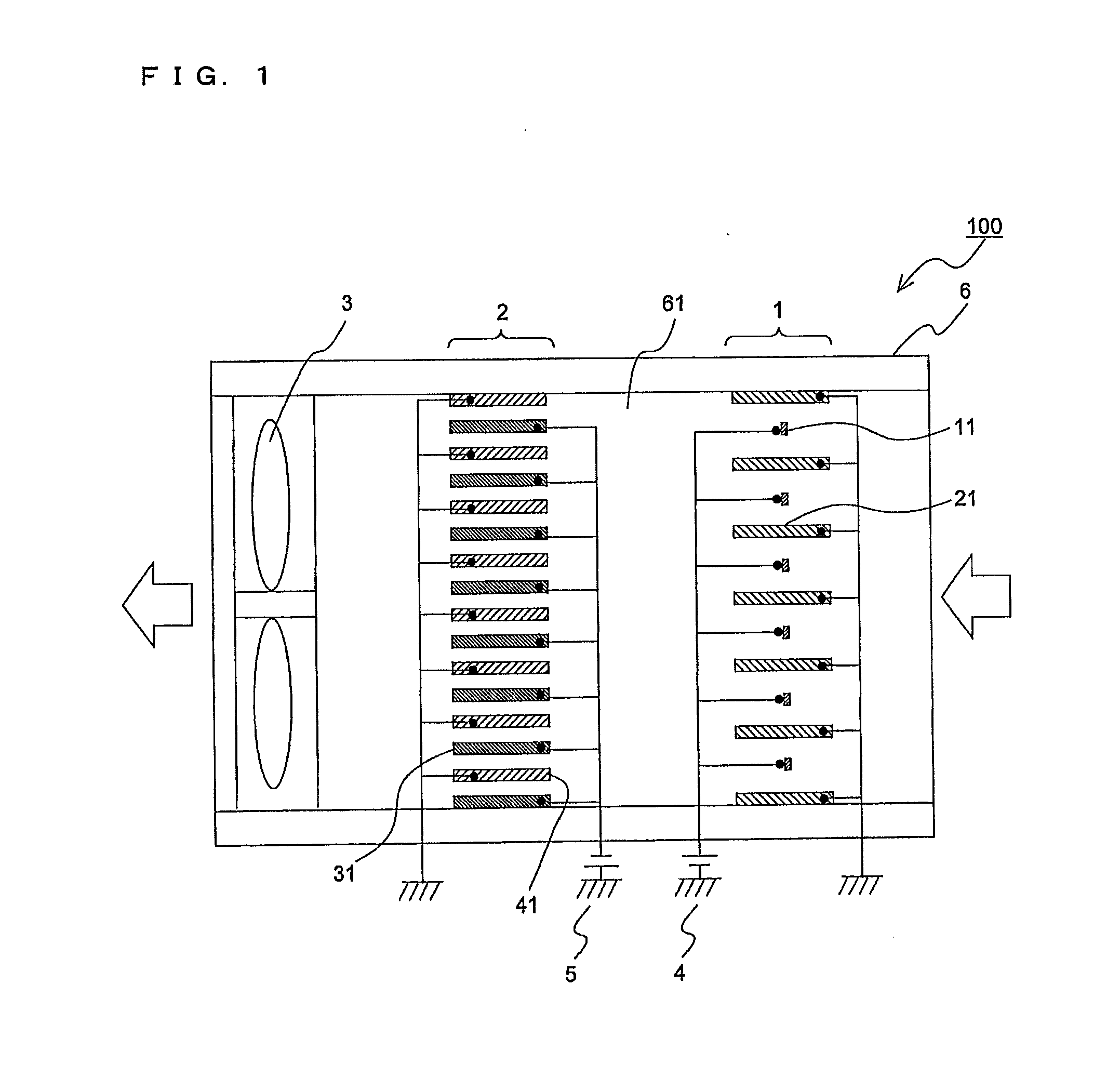
[0041]FIG. 1 is a schematic view of a corona discharge device (hereinafter referred to as a device 100) according to Embodiment 1. With reference to FIG. 1, the structure and operation of the device 100 will be described. In FIG. 1 and subsequent drawings, the dimensional relationships among components are sometimes different from the actual ones. Further, in FIG. 1, the flow of air is shown by arrows.
[Device 100]
[0042]The device 100 is an electric dust collection device that cleans the space by capturing particles (hereinafter referred to as suspended particles) and microbes and viruses (hereinafter suspended microbes) that are suspended in air flowing in the device 100 and supplying the air to the outside after the suspended particles and suspended microbes are captured from the air. The device 100 includes an air-path housing 6 having therein an air path 61 through which air flows. In the air path 61, a charging section 1, a capturing section 2, and a fan 3 are disposed.
[0043]The...
embodiment 2
[0072]While the single charging-section ground electrode unit 20 is provided in Embodiment 1 described above, a description will be given of Embodiment 2 in which a plurality of charging-section ground electrode units 20 are provided. Another structure example of charging-section ground electrodes according to Embodiment 2 will be described with a focus on differences from Embodiment 1. Embodiment 2 can be combined with Embodiments described below.
[0073]FIG. 7 is an exploded perspective view illustrating a structure of a charging section according to Embodiment 2. As illustrated in FIG. 7, a charging section 1 includes two charging-section ground electrode units 20 (sometimes distinctively referred to as a charging-section ground electrode unit 20a and a charging-section ground electrode unit 20b). The charging-section ground electrode unit 20a and the charging-section ground electrode unit 20b are superposed such that charging-section ground electrodes 21 of the charging-section gr...
embodiment 3
[0088]Embodiment 3 will be described with a focus on differences of another exemplary structure of a charging section from that adopted in Embodiment 1. Embodiment 3 can be combined with Embodiments described below.
[0089]FIG. 11 is a rear view of a charging-section high-voltage electrode unit according to Embodiment 3.
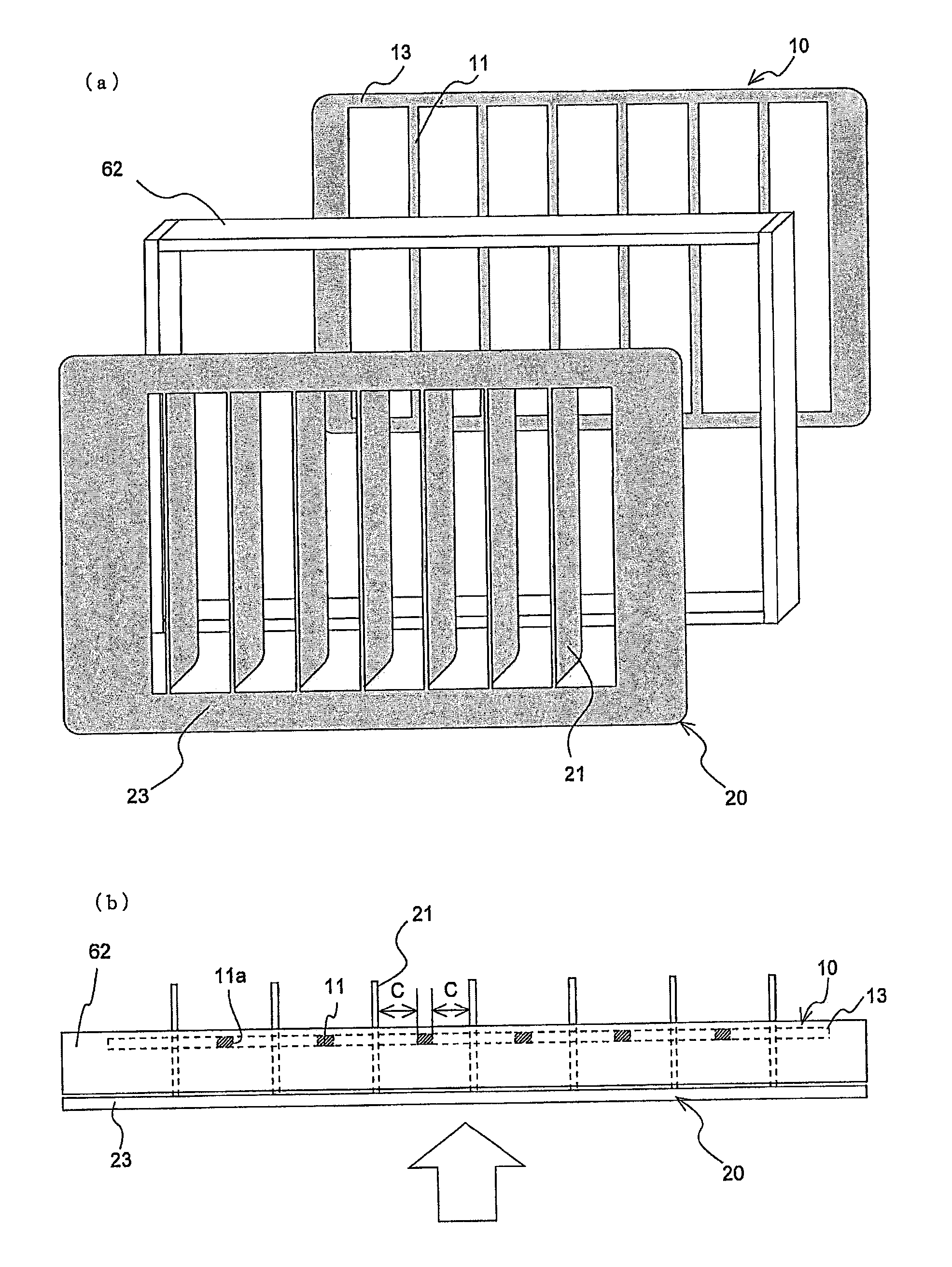
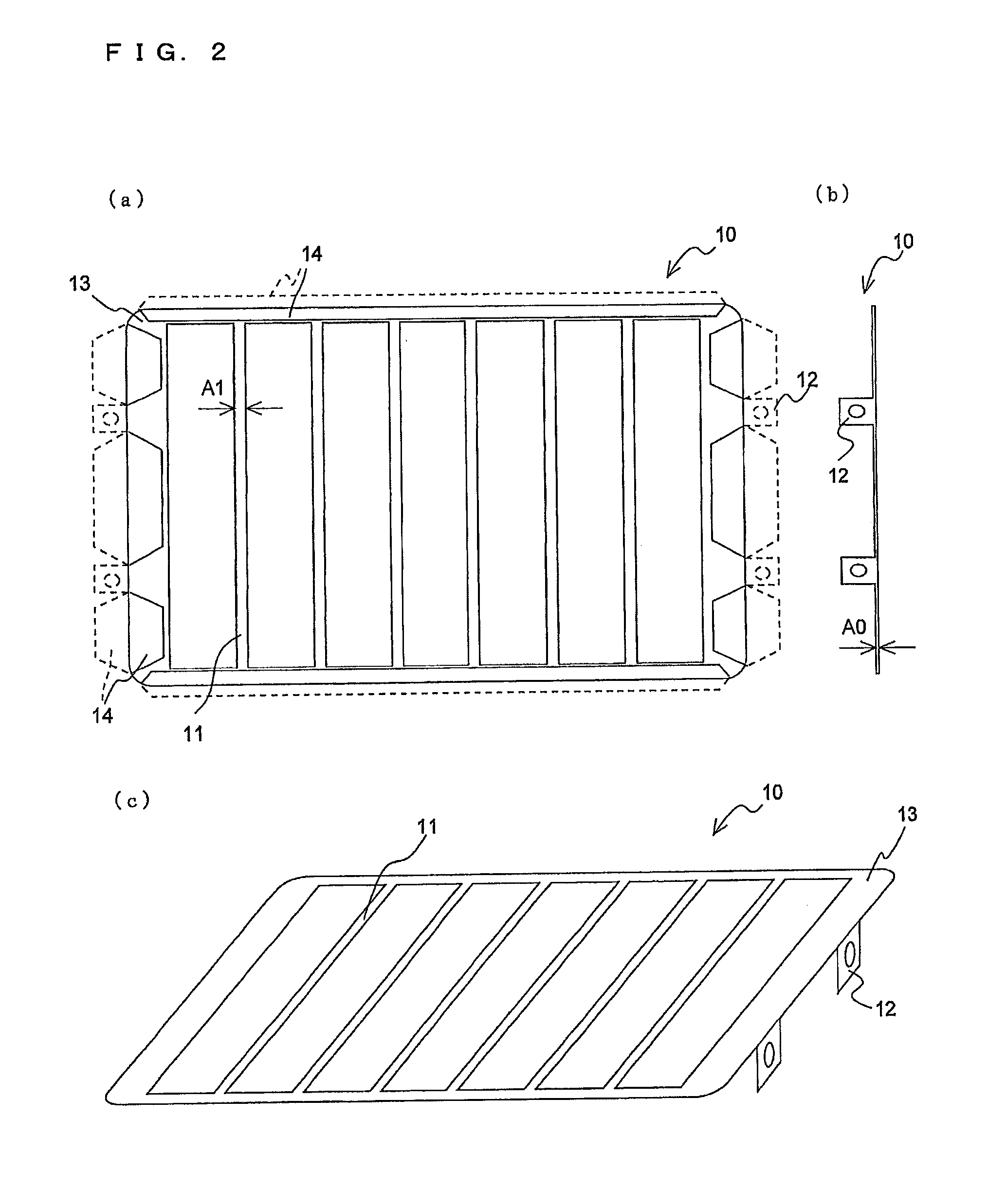
[0090]In Embodiment 1 illustrated in FIG. 6, the support portions 12 provided on the charging-section high-voltage electrode unit 10 are attached to the frame member 62 with the insulators 7 being disposed therebetween. In Embodiment 3, a charging-section high-voltage electrode unit 10 is assembled without forming support portions 12 and insulators 7. As illustrated in FIG. 11, the charging-section high-voltage electrode unit 10 is attached to be superposed on an insulating body 8 shaped like a frame-shaped rectangular flat plate. The width and height dimensions of the rectangular frame shape of the insulating body 8 are large enough to include a frame portion 13 of th...
PUM
 Abstract
Description
Claims
Application Information
 - R&D
- Intellectual Property
- Life Sciences
- Materials
- Tech Scout
- Unparalleled Data Quality
- Higher Quality Content
- 60% Fewer Hallucinations
Browse by: Latest US Patents, China's latest patents, Technical Efficacy Thesaurus, Application Domain, Technology Topic, Popular Technical Reports.
© 2025 PatSnap. All rights reserved.Legal|Privacy policy|Modern Slavery Act Transparency Statement|Sitemap|About US| Contact US: help@patsnap.com


