Pressure-balance valve for balancing fluid feed to actuator cylinders of a servo-control for controlling rotor blades of a rotorcraft

Active Publication Date: 2015-10-15
EUROCOPTER
View PDF1 Cites 5 Cited by
  • Summary
  • Abstract
  • Description
  • Claims
  • Application Information

AI Technical Summary

Benefits of technology

[0088]Such an escape may potentially be caused under the effect of thrust exerted by the fluid present in the chamber in the event of the pressure of the fluid present in the chamber being excessive compared with the fluid flowing in the first duct.
[0089]These provisions are such that an escape of the shutter towards the perforated seat prevents fluid passing from the first duct towards the chamber in the event of excess pressure of the fluid present in the chamber. When the pressure of the fluid present in the chamber becomes lower than the pressure of the fluid admitted into the first duct, then the shutter is put

Problems solved by technology

In this context, aviation leads to a problem of ensuring an aircraft is safe, even in the event of a failure of servo-controls used to drive a member for varying the attitude of the aircraft under the effect of flight commands issued by a pilot.
Such a constraint arises in particular because of the need to maintain complete separation between the hydraulic circuits that are independently feeding each of the actuator cylinders of the servo-control having multiple actuator cylinders.
Nevertheless, the organization of the pressure-balance balance valve described in Document U.S. Pat. No. 4,825,748 does not enable the respective hydraulic fluid feed circuits to be rigorously segregated between the two servo-controls.
More particularly, specifically for servo-controls, malfunction is potentially due to a dormant failure in

Method used


Image

  • Pressure-balance valve for balancing fluid feed to actuator cylinders of a servo-control for controlling rotor blades of a rotorcraft
  • Pressure-balance valve for balancing fluid feed to actuator cylinders of a servo-control for controlling rotor blades of a rotorcraft
  • Pressure-balance valve for balancing fluid feed to actuator cylinders of a servo-control for controlling rotor blades of a rotorcraft

Examples


Embodiment Construction

[0116]For a better understanding of the explanations below, members that are common and shown in various figures are respectively identified in the description relating specifically to those figures using the same reference numbers and / or letters, but without that meaning that they are shown individually in each of the figures.

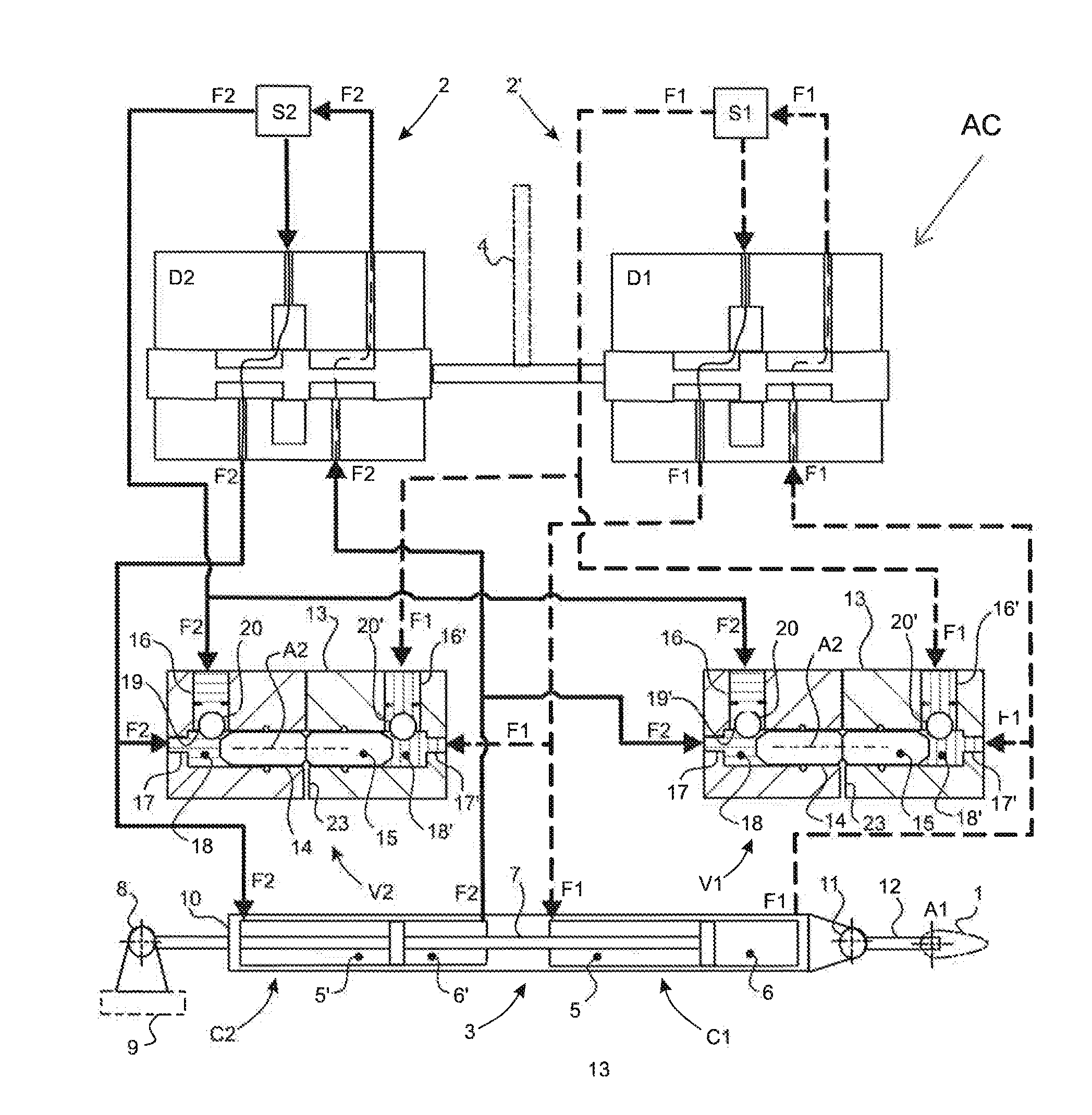
[0117]In FIG. 1, a hydraulic installation is dedicated to pivotally moving the blades 1 of a rotary wing aircraft AC. In this example, the rotary wing aircraft AC is a rotorcraft having blades 1 that pivot about their respective pitch variation axes A1.

[0118]Conventionally, such a hydraulic installation comprises two distinct hydraulic circuits 2 and 2′ causing respective fluids F1 and F2 to flow between fluid sources S1 and S2 associated with respective ones of the hydraulic circuits 2 and 2′, and respective actuator cylinders C1 and C2 of a servo-control 3.

[0119]The hydraulic installation also typically includes hydraulic directional-control valves Dl and D2...


PUM


Abstract

A pressure-balance valve for balancing the pressures of fluids admitted into the pressure-balance valve via respective second ducts. The pressure-balance valve has both a chamber for guiding movement in translation of a piston, and also fluid flow paths, each comprising a said second duct and a first duct for admitting a fluid coming from the same fluid source as the fluid flowing in its second duct. Each of the first ducts is provided with a shutter co-operating with a ramp arranged on the piston. Movement of the piston in translation as a result of a pressure difference between the fluids respectively admitted into the second ducts causes one of the shutters to slide along the corresponding ramp and consequently allows additional fluid to be delivered from a first duct to the second duct of the same fluid flow path.

Description

CROSS REFERENCE TO RELATED APPLICATION[0001]This application claims priority to French patent application No. FR 14 00886 filed on Apr. 11, 2014, the disclosure of which is incorporated in its entirety by reference herein.BACKGROUND OF THE INVENTION[0002](1) Field of the Invention[0003]The present invention relates to the field of rotary wing aircraft having at least one rotor driven in rotation by a power plant. The present invention relates more particularly to devices for synchronizing the movement of hydraulic members forming parts of the rotorcraft rotors for the purpose of varying the aerodynamic angle of incidence of the airfoils of the blades of such a rotor.[0004](2) Description of Related Art[0005]Rotorcraft are fitted with at least one main rotor of substantially vertical axis providing the rotorcraft at least with lift. In the specific circumstance of a helicopter, the main rotor also provides the rotorcraft with propulsion and guidance in pitching and in roll.[0006]Roto...

Claims


Application Information

Patent Timeline
IPC IPC(8): F15B13/02B64C27/58
CPCB64C27/58F15B13/026F15B11/22F15B18/00B64C27/64F15B2211/5155F15B2211/8757F15B2211/5154F15B2211/5152F15B2211/57F15B2211/50572
Inventor MARGER, THIBAUTGROLL, ARNAUDBIHEL, JEAN-ROMAINCOIC, CLEMENT
Owner EUROCOPTER
Why Eureka
Try Eureka