Method and device for optimizing a magnetic resonance sequence

a magnetic resonance sequence and optimization method technology, applied in the direction of reradiation, measurement using nmr, instruments, etc., can solve the problem of high level of loudness of magnetic resonance scanners, and achieve the effect of optimizing the magnetic resonance sequen

Active Publication Date: 2015-10-15
SIEMENS HEALTHCARE GMBH
View PDF9 Cites 9 Cited by
  • Summary
  • Abstract
  • Description
  • Claims
  • Application Information

AI Technical Summary

Benefits of technology

[0007]An object of the invention is to provide effective optimization of a magnetic resonance sequence, particularly with regard to optimizing of the slew rates of gradient switching sequences of the magnetic resonance sequence.

Problems solved by technology

The gradient switching sequences specified by the magnetic resonance sequence can lead to the magnetic resonance scanner having a high level of loudness during the acquisition of the magnetic resonance data.

Method used


Image

  • Method and device for optimizing a magnetic resonance sequence
  • Method and device for optimizing a magnetic resonance sequence
  • Method and device for optimizing a magnetic resonance sequence

Examples


first embodiment

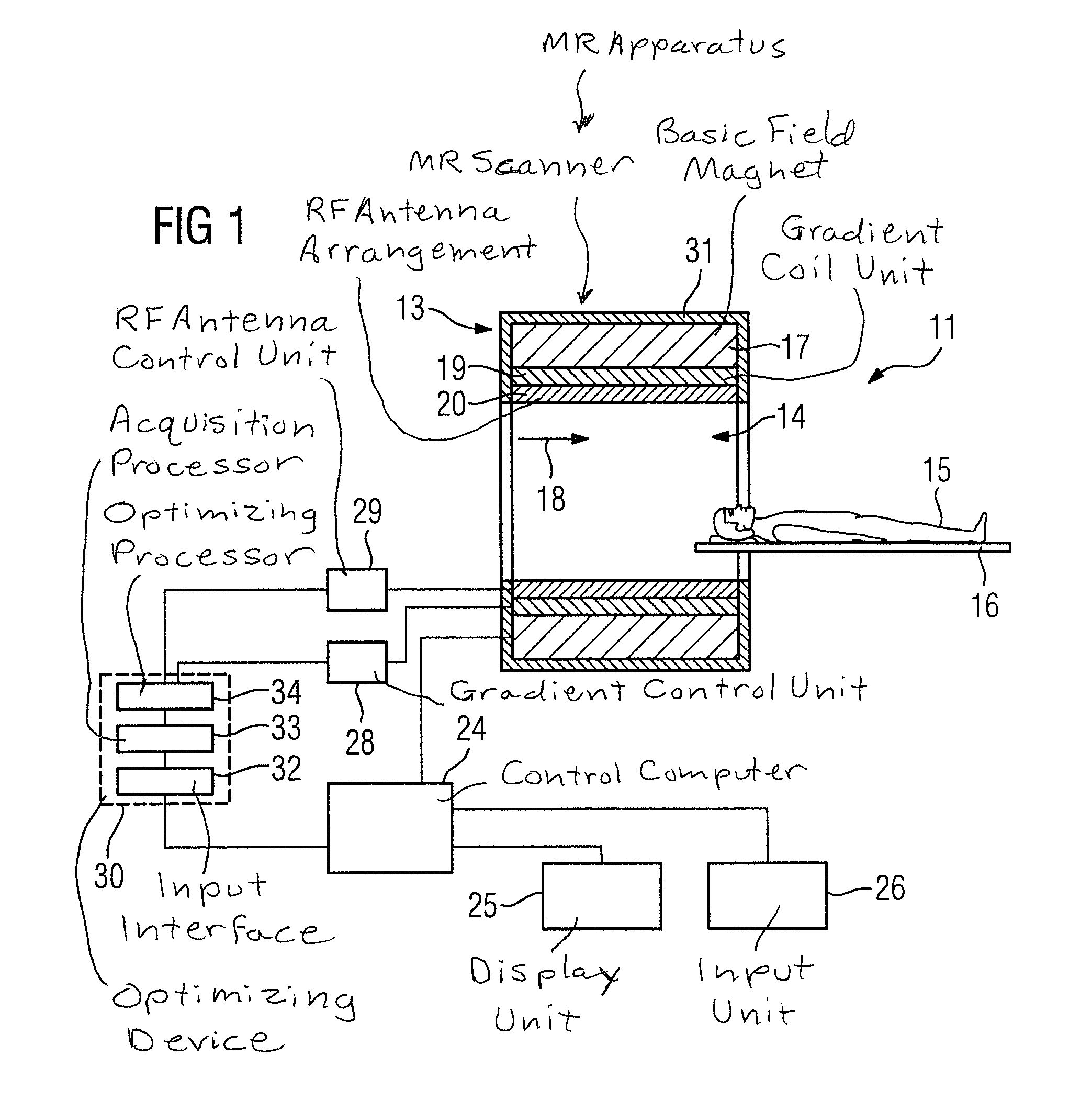
[0042]FIG. 2 is a flowchart of the method according to the invention. In the embodiments shown in FIGS. 2 and 3, the optimization of the magnetic resonance sequence takes place largely automatically. Alternatively, it is also possible for method steps which take place automatically in the embodiments of FIGS. 2 and 3, to be carried out manually and vice versa.

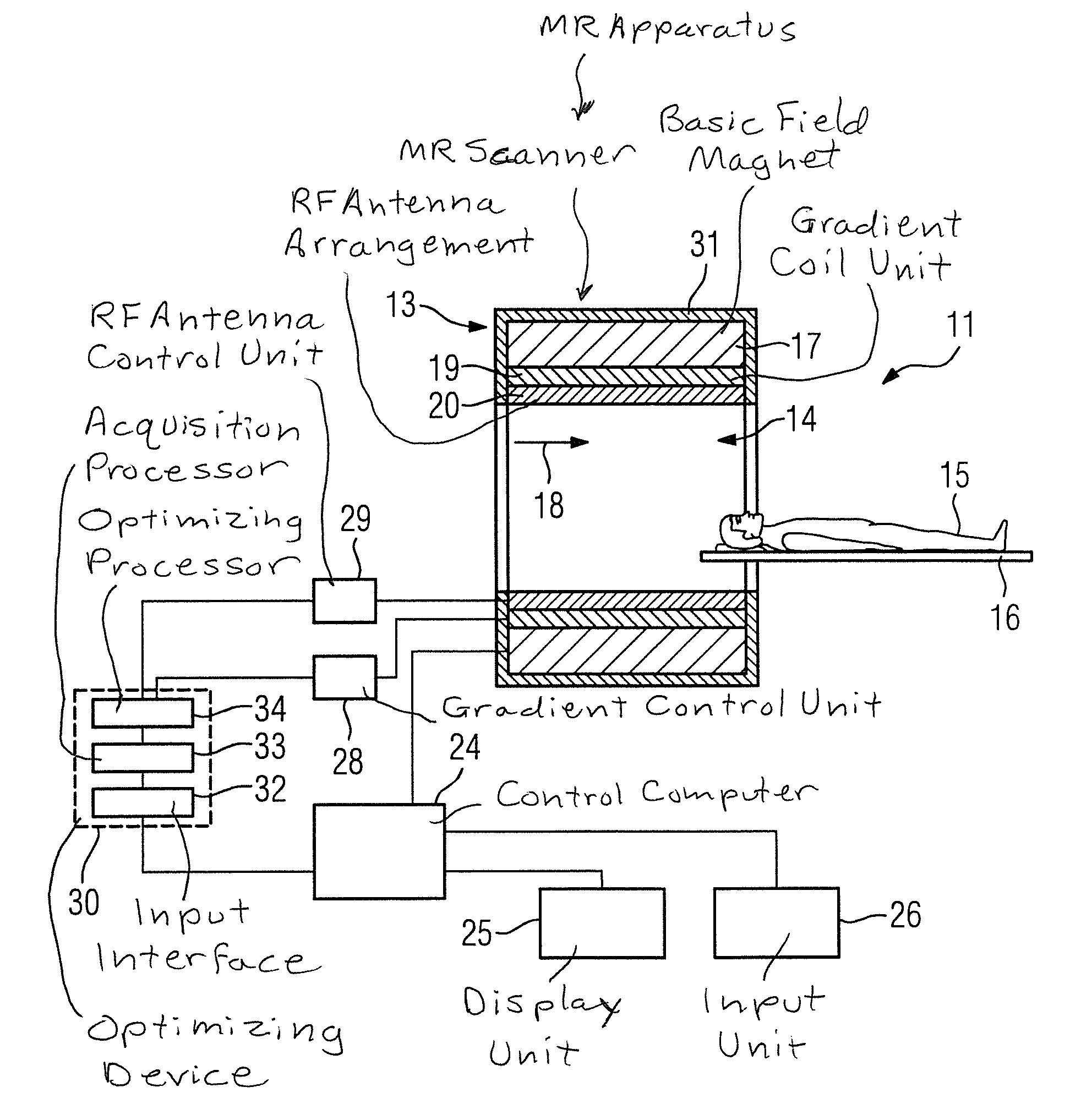
[0043]In a first method step 39, initially a selection and preparation of a magnetic resonance sequence of the magnetic resonance device 11 is carried out in the usual way. This means that typically a user stipulates, via the input unit 26, the type of magnetic resonance sequence and / or seeks a suitable protocol in which a particular magnetic resonance sequence is defined. The protocols contain various imaging parameters for the respective magnetic resonance sequence. These imaging parameters include particular basic data for the desired magnetic resonance sequence, for example, the type of magnetic resonance sequence, that is,...

second embodiment

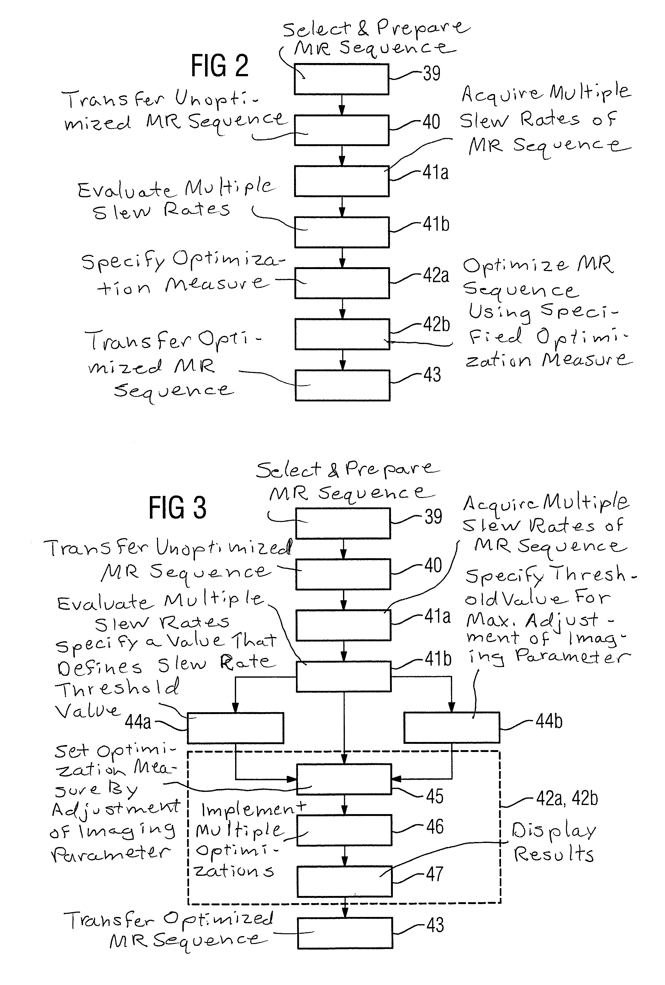
[0049]FIG. 3 shows a flowchart of the method according to the invention.

[0050]The following description is essentially restricted to the differences from the exemplary embodiment in FIG. 2 wherein, with regard to method steps which remain the same, reference can be made to the description of the exemplary embodiment in FIG. 2. In principle, the same method steps are essentially identified with the same reference signs.

[0051]The second embodiment of the method according to the invention shown in FIG. 3 essentially includes the method steps 39, 40, 41a, 41b, 42a, 42b, 43 of the first embodiment of the method according to the invention as shown in FIG. 2. The second embodiment of the method according to the invention shown in FIG. 3 has further method steps and sub-steps. Also conceivable is an alternative method sequence to that of FIG. 3, which has only part of the additional method steps and / or sub-steps represented in FIG. 2. Naturally, an alternative method sequence to that of FIG...


PUM


Abstract

In order to provide an effective optimization of a magnetic resonance sequence, particularly with regard to optimizing the slew rates of gradient switching sequences of the magnetic resonance sequence, in a method for optimizing a magnetic resonance sequence of a magnetic resonance apparatus, wherein the magnetic resonance sequence includes multiple pre-set gradient switching sequences with multiple pre-set slew rates, the multiple pre-set slew rates are provided to a computer wherein the multiple pre-set slew rates are evaluated. At least one optimization measure for the magnetic resonance sequence is defined based on the evaluation of the multiple pre-set slew rates. The magnetic resonance sequence is optimized based on the at least one pre-set optimization measure, wherein the optimized magnetic resonance sequence has multiple optimized gradient switching sequences with multiple optimized slew rates, and the multiple optimized slew rates being optimized in relation to the multiple pre-set slew rates.

Description

BACKGROUND OF THE INVENTION[0001]1. Field of the Invention[0002]The invention relates to a method for optimizing a magnetic resonance sequence for operating a magnetic resonance apparatus, a method for operating a magnetic resonance apparatus, a sequence optimizing device, a magnetic resonance apparatus and a storage medium encoded with programming instructions that cause a computer to implement such a method.[0003]2. Description of the Prior Art[0004]In a magnetic resonance apparatus, also known as a magnetic resonance tomography system, the body of the subject to be examined, particularly that of a patient, is typically exposed to a relatively strong magnetic field of, for example, 1.5 or 3 or 7 Tesla, with the use of a basic field magnet of a scanner in which the subject is situated. In addition, gradient switching sequences are activated by a gradient coil arrangement of the scanner. By operation of a radio frequency antenna in the scanner, using suitable antenna devices, radio ...

Claims


Application Information

Patent Timeline
Patent Type & Authority Applications(United States)
IPC IPC(8): G01R33/38G01R33/54
CPCG01R33/543G01R33/38G01R33/3854G01R33/4816G01R33/4818G01R33/482G01R33/4822G01R33/4824G01R33/4826G01R33/4828G01R33/483G01R33/4831
Inventor PAUL, DOMINIKROLAND, JOERG
Owner SIEMENS HEALTHCARE GMBH
Why Eureka
Try Eureka