Device and method for stretching or compressing laser pulses

a laser pulse and laser pulse technology, applied in the direction of laser details, instruments, electrical equipment, etc., can solve the problems of limited efficiency and precision of spectral fourier plane manipulation, and low stability of spatial and temporal pulse properties, so as to facilitate the out-coupling of stretched pulses and avoid wavelength dependence of focusing laser pulses

Active Publication Date: 2015-10-15
DEUTES ELEKTRONEN SYNCHROTRON DESY +1
View PDF2 Cites 5 Cited by
  • Summary
  • Abstract
  • Description
  • Claims
  • Application Information

AI Technical Summary

Benefits of technology

[0024]Advantageously, a chromatic aberration of the focusing lens(es) does not impair the improved light modulation in the Fourier plane. Otherwise, the wavelength dependency of focusing the laser pulses can be avoided by using focusing mirror(s), having e. g. a parabolic mirror surface. Preferably, the light modulator 20 is arranged in a focus of the focusing device corresponding to a central wavelength of the laser pulses.
[0025]The shaper unit spans a beam path from the first dispersive element via the second dispersive element to the mirror (forward beam path) and back from the mirror via the second dispersive element to the first dispersive element (return beam path). According to a preferred embodiment of the invention, the forward and return beam paths can be slightly displaced relative to each other, so that an input side of the forward beam path and an output side of the return beam path are shifted relative to each other. Advantageously, this facilitates the out-coupling of the stretched pulses. Due to the deflections with the dispersing elements, each of the forward and return beam path sections spans a plane, and the displacement may include a parallel displacement of the forward and return beam path planes or a mutual tilting thereof.

Problems solved by technology

The 4-f-geometry has disadvantages in terms of a long beam path and therefore low stability of the spatial and temporal pulse properties.
As a further disadvantage, a large amount of additional higher-order dispersion is added to the laser pulses, which may result in problems with the re-compression thereof.
Accordingly, the manipulation in the spectral Fourier plane has a limited efficiency and precision only.
This disadvantage even would be kept if the Fourier plane including the diffusive line would be imaged, e. g. with a cylinder lens onto the phase mask (as proposed in [8]) as the spatial resolution could not be improved by the focusing.

Method used


Image

  • Device and method for stretching or compressing laser pulses
  • Device and method for stretching or compressing laser pulses

Examples


Embodiment Construction

[0015]The objective of the invention is to provide an improved shaper device for temporal shaping ultrashort light pulses being capable of avoiding disadvantages of conventional techniques. In particular, it is an objective of the invention to provide a stretcher or compressor device with a compact design and an improved control of the spectral phase and amplitude of the light pulses, in particular with improved spectral resolution. Another objective of the invention is to provide an improved method for shaping ultrashort light pulses avoiding disadvantages and limitations of conventional techniques and in particular being capable of manipulating the spectral phase and amplitude of stretched or compressed light pulses with improved spatial and spectral resolution.

[0016]These objectives are solved with a shaper device and a shaping method of the invention.

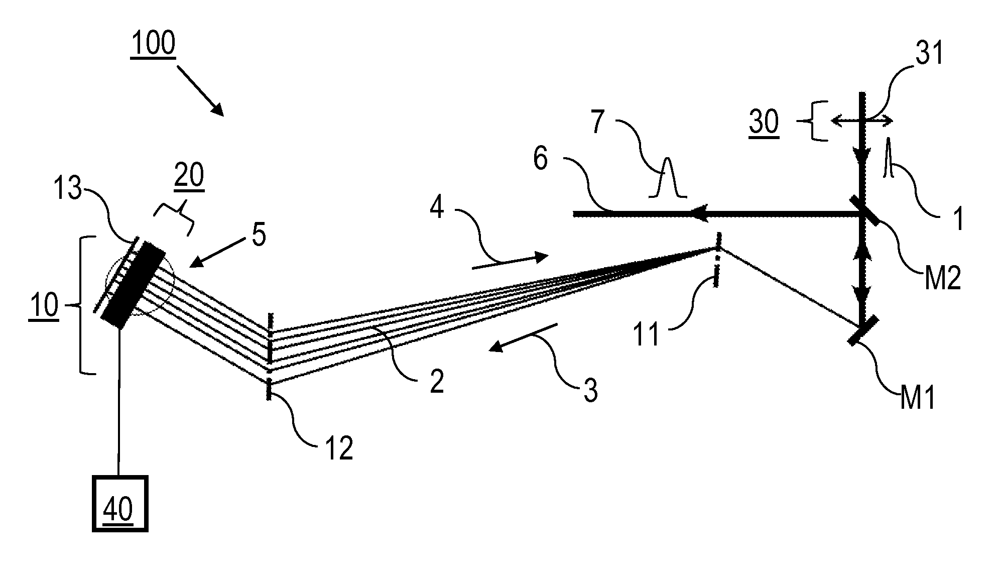
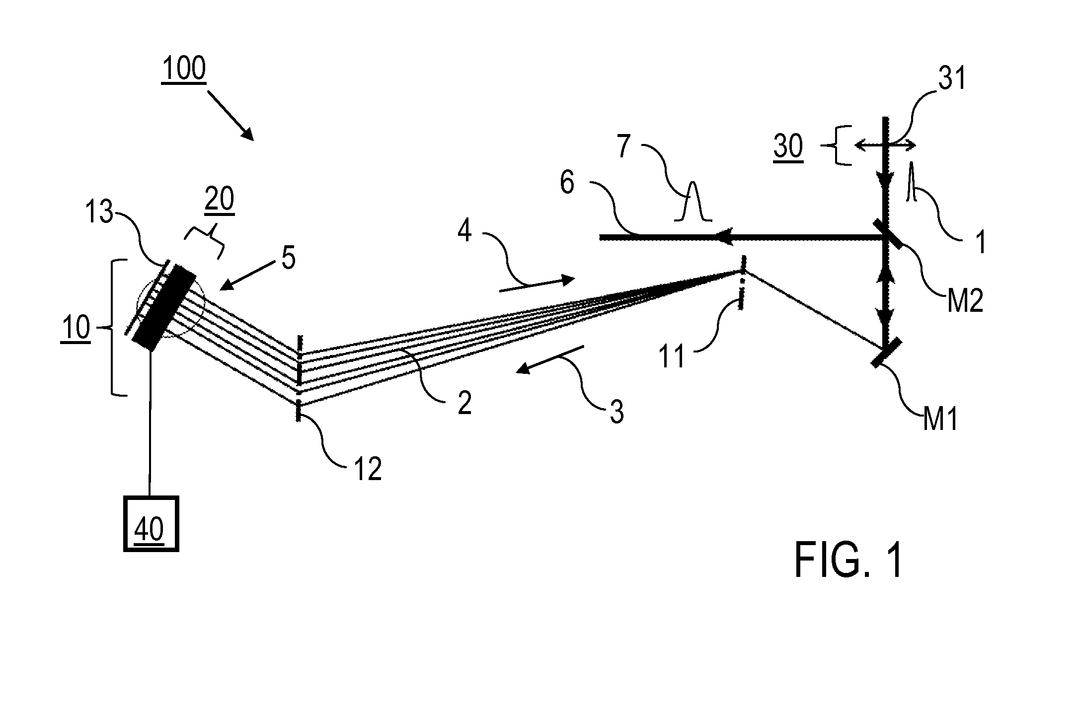
[0017]According to a first general aspect of the invention, a laser pulse shaper device with negative dispersion is provided, whic...


PUM


Abstract

A laser pulse shaper device includes shaper unit including first dispersive element for spatially separating spectral components of laser pulses, second dispersive element for parallelizing and deflecting spectral components into Fourier plane of dispersive elements, and mirror for back-reflecting of laser pulses via dispersive elements, and light modulator in Fourier plane of dispersive elements, which is capable of modulating spectral components of laser pulses, wherein beam path of shaper unit includes forward beam path from first dispersive element via second dispersive element to mirror and return beam path from mirror via second dispersive element to first dispersive element, and focusing device is arranged at input side of forward beam path before first dispersive element for focusing spatially separated spectral components of laser pulses to Fourier plane of dispersive elements. Furthermore, a method for stretching or compressing laser pulses is described.

Description

BACKGROUND OF THE INVENTION[0001]The invention relates to a laser pulse shaper device, which is configured for shaping laser pulses, in particular to a laser pulse shaper device including a shaper unit with dispersive elements and a light modulator for spectrally resolved modulating spectral components of the laser pulses. Furthermore, the invention relates to a shaping method for shaping laser pulses, in particular using an arrangement of dispersive elements and including a spectrally resolved modulation of the laser pulses. Applications of the invention are available in optical set-ups for stretching or compressing laser pulses, in particular in pulse amplifiers.[0002]For describing the background of the invention, particular reference is made to the following publications:[0003][1] R. L. Fork et al. in “Optics Letters” vol. 9, 1984, p. 150-152;[0004][2] R. Naganuma et al. in “Optics Letters” vol. 16, 1991, p. 738-740;[0005][3] U.S. Pat. No. 8,514,898 B1;[0006][4] US 2001 / 026 105 ...

Claims


Application Information

Patent Timeline
Patent Type & Authority Applications(United States)
IPC IPC(8): H01S3/00G02B26/06G02B27/09
CPCH01S3/0057G02B27/0905H01S3/0085G02B27/0977G02B27/0972G02B27/0944G02B26/06G02B26/0825
Inventor RIEDEL, ROBERTTAVELLA, FRANZSCHULZ, MICHAELPRANDOLINI, MARK JAMES
Owner DEUTES ELEKTRONEN SYNCHROTRON DESY
Why Eureka
Try Eureka