

Overmolded Flux Ring
a technology of flux rings and eddycurrent fans, which is applied in the direction of machines/engines, asynchronous induction clutches/brakes, liquid fuel engines, etc., can solve the problems of reducing efficiency, reducing product effectiveness, and not generally desirable for such fan assemblies to be run continuously, so as to reduce temperature, reduce stress and hoop loads, and be effective.
Active Publication Date: 2015-10-15
BORGWARNER INC
View PDF8 Cites 3 Cited by
- Summary
- Abstract
- Description
- Claims
- Application Information
AI Technical Summary
Benefits of technology
This patent describes improved methods, structures, and systems for making and using flux rings for eddy-current assemblies. The flux rings are designed to cool better, minimize stress and hoop loads, and become more durable and long-lasting. One aspect of the invention includes a metal base member and a flexible arm member that connect to a separate annular ring member made of aluminum. The annular member is overmolded with sections that have ribs and vanes to improve heat distribution. The base member has ventilation openings to allow air circulation and cooling. Other features include openings on the outer annular ring to minimize hoop loads and stress.
Problems solved by technology
It is not generally desirable for such fan assemblies to be run continuously.
Additionally, continuous high speed operation when unnecessary places a non-required draw on the engine and thereby reduces efficiency.
Not only can the heat reduce the effectiveness of the product, but the heat over time can expand and distort the flux ring, reducing both the durability and life of the product.
Method used
View moreImage
Smart ImageViewing Examples

Examples
embodiment 300
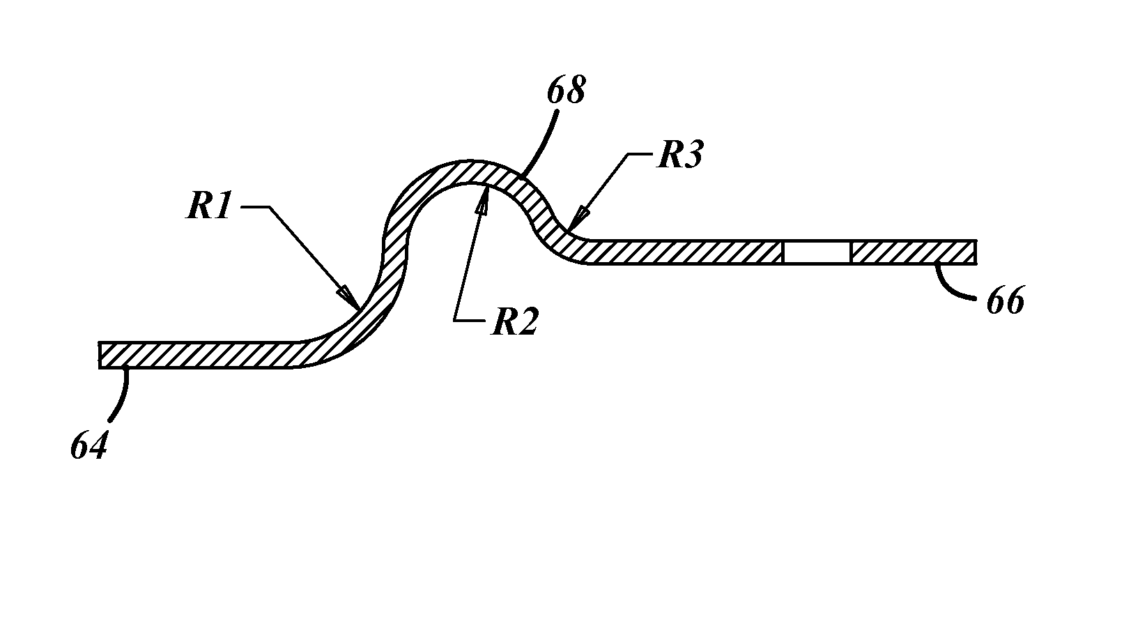
[0059]It is also possible to provide the overmolded sections with overlapping “zig-zag” configurations, as shown in FIG. 15. This flux ring embodiment 300 is essentially the same as the flux ring embodiments 50 and 200 discussed above, but with different side edges 302 and different air gaps 304 between the overmolded sections 310. The hub member and spoked air members can be the same as or similar to the other embodiments discussed above. The overmolded sections 310 also preferably have cooling fins or vanes 320 on one or both sides.
Login to View More PUM
| Property | Measurement | Unit |
|---|---|---|
| temperature | aaaaa | aaaaa |
| temperature | aaaaa | aaaaa |
| flexible | aaaaa | aaaaa |
Abstract
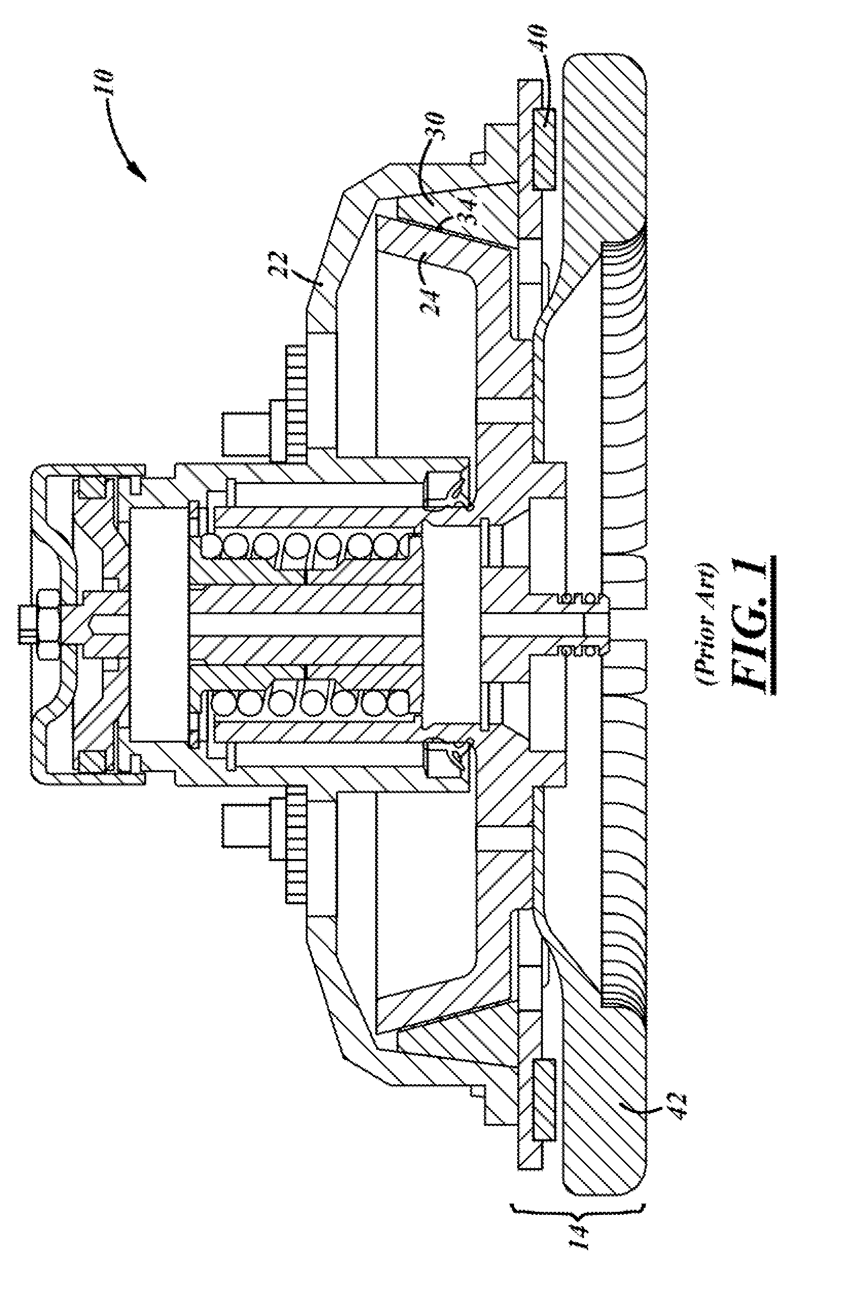
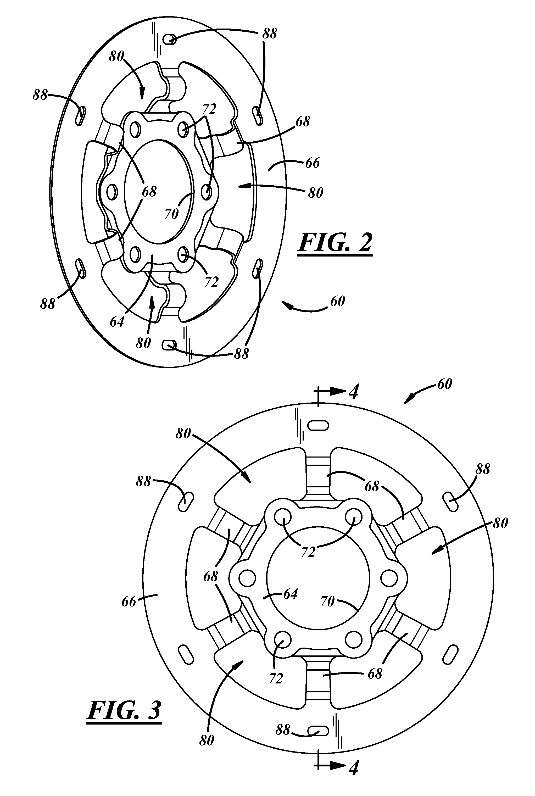
An overmolded steel flux ring member for an eddy-current fan drive assembly. The flux ring member includes a base member having a hub member, an annular outer ring member, and a plurality of connecting arm members. An overmolding material, such as aluminum, is overmolded on the annular outer ring member preferably in separate sections. Ventiliation openings in said base member allow air to flow past a magnet ring for cooling.
Description
CROSS REFERENCE TO RELATED APPLICATIONS[0001]This application claims the benefit of U.S. Provisional Application Ser. No. 61 / 978,844, filed Apr. 12, 2014, which is incorporated herein by reference.TECHNICAL FIELD[0002]The present invention is related to two-speed fan drive assemblies, and more particularly to flux rings for eddy-current fan drive assemblies.BACKGROUND OF THE INVENTION[0003]Vehicle engines commonly utilize cooling assemblies to remove excess heat from the engine and maintain an optimal operating temperature. The cooling assembly pumps a coolant through the engine and other components in order to control engine temperature. Heat generated within the engine and other components is absorbed by the coolant and dispersed into the surrounding atmosphere through the use of a radiator. In order to improve dispersal by the radiator, it is common to utilize fan assemblies to draw or force air past the radiator to assist in heat transfer.[0004]It is not generally desirable for ...
Claims
Login to View More Application Information
Patent Timeline
 Patent Type & AuthorityApplications(United States)
IPC IPC(8): H02K49/04F04D25/06F04D19/00
CPCH02K49/046F04D25/06F04D19/002F04D25/08F04D29/181F05D2230/21F05D2300/121F05D2300/171
InventorSTAGG, JONATHAN B.SHOLAPURKAR, SANJEEV S.SETTINERI, SAMUEL E.
OwnerBORGWARNER INC