Power supply device for vehicle performing regenerative braking

a technology of regenerative braking and power supply device, which is applied in the direction of capacitor propulsion, battery, cell component, etc., can solve the problems of increasing the temperature of the battery and demeriting the inability to safely use the sub-battery, so as to reduce the degradation of the lead-acid battery by large current, increase the output, and efficient radiation

Active Publication Date: 2015-10-22
SANYO ELECTRIC CO LTD
View PDF9 Cites 18 Cited by
  • Summary
  • Abstract
  • Description
  • Claims
  • Application Information

AI Technical Summary

Benefits of technology

[0006]In the power supply device described in these patent literatures, a lithium ion secondary battery is connected in parallel to the lead-acid battery. The power supply device where the lithium ion secondary battery is connected in parallel to the lead-acid battery, is efficiently charged with regenerative generation power. In addition, as the power supply device divides a large current from the lead-acid battery to the lithium ion secondary battery and charges at regenerative braking, it makes charging current of the lead-acid battery decreased, and degradation of the lead-acid battery can be reduced.
[0007]The power supply device where the sub-battery such as the lithium ion secondary battery is connected in parallel to the lead-acid battery, makes charging resistance as internal resistance at the time of charging the sub-battery smaller than that of the lead-acid battery, and can make charge current of the sub-battery at regenerative braking large. Making charging current of the sub-battery large is to make charging current of the lead-acid battery small at regenerative braking, and then the degradation of the lead-acid battery can be suppressed. However, in this power supply device, each time the vehicle is stopped by regenerative braking due to waiting for a traffic light, as the lead-acid battery and the sub-battery are charged with large current, the battery temperature is increased by heat generation in the lead-acid battery and the sub-battery due to Joule heat. Especially, in order to make charging current smaller at regenerative braking, charging resistance of the sub-battery is made small, and charging current of the sub-battery is made large. In such a power supply device, the temperature of the sub-battery through which a large charging current flows is more increased. When the temperature of the sub-battery is increased, charging resistance of the sub-battery becomes small, and then charging current at regenerative braking becomes larger, and heat generation in the sub-battery due to Joule heat is more increased. The temperature increase of the sub-battery has an effect that charging current of the lead-acid battery is decreased and its degradation can be reduced. However, as when the temperature of the sub-battery is abnormally increased, there is a demerit that the sub-battery cannot be safely used. Further, since the sub-battery such as the nickel hydride battery, the lithium ion secondary battery, and the electric double layer capacitor is more expensive than the lead-acid battery, it is important that not only the short life of the lead-acid battery, but also the abnormal degradation of the sub-battery is prevented.
[0008]The present disclosure is developed for the purpose of preventing the abnormal temperature increase of the power storage device configuring the sub-battery. One non-limiting and explanatory embodiment provides a power supply device for a vehicle performing regenerative braking in which while the degradation of the lead-acid battery is reduced and its life is prolonged without complicated cooling mechanism such as forcible cooling, the abnormal temperature increase of the power storage device is also prevented.

Problems solved by technology

However, in this power supply device, each time the vehicle is stopped by regenerative braking due to waiting for a traffic light, as the lead-acid battery and the sub-battery are charged with large current, the battery temperature is increased by heat generation in the lead-acid battery and the sub-battery due to Joule heat.
However, as when the temperature of the sub-battery is abnormally increased, there is a demerit that the sub-battery cannot be safely used.

Method used


Image

  • Power supply device for vehicle performing regenerative braking
  • Power supply device for vehicle performing regenerative braking
  • Power supply device for vehicle performing regenerative braking

Examples


Embodiment Construction

[0022]Hereinafter, the embodiment of the present invention will be described referring to drawings. However, the following embodiments illustrate a power supply device for a vehicle performing regenerative braking which is aimed at embodying the technological concept of the present invention, and the present invention is not limited to the power supply device for a vehicle performing regenerative braking described below. Further, the members illustrated in Claims are not limited to the members in the embodiments.

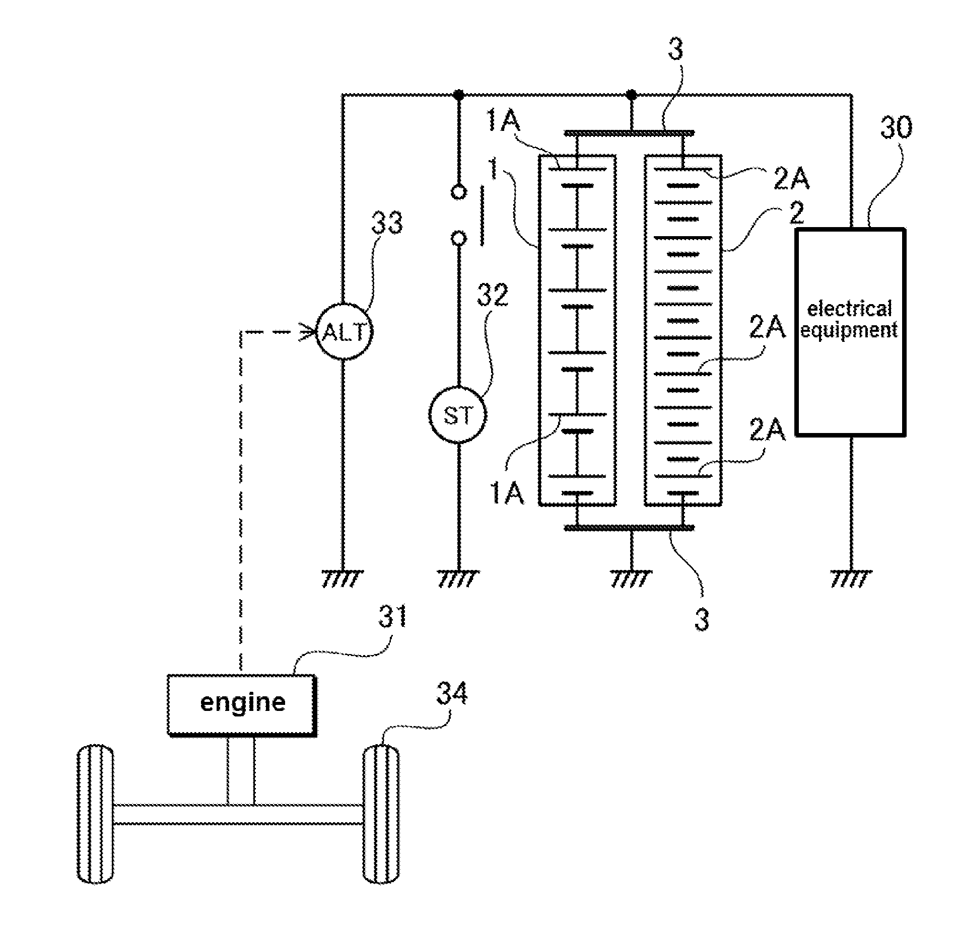
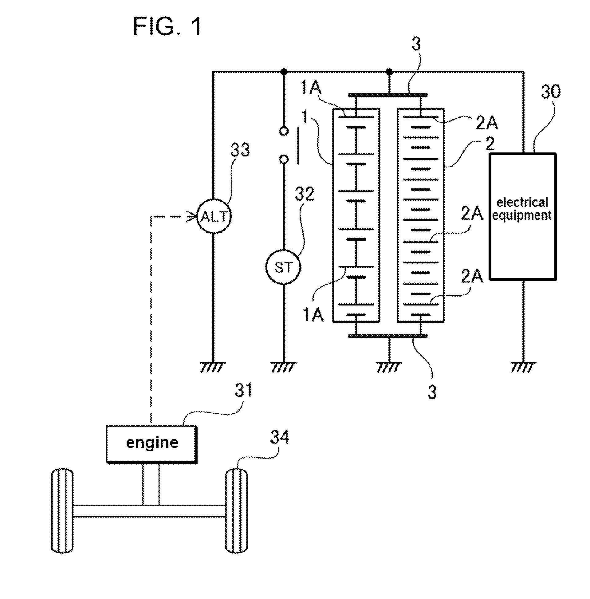
[0023]The power supply device shown in a block diagram of FIG. 1, is installed in the vehicle performing regenerative braking. Preferably, it is installed in the vehicle having a regenerative braking function and an idle stop (idle reduction) function. This power source device includes a lead-acid battery 1 and a power storage device 2. The lead-acid battery 1 and the power storage device 2 are connected in parallel, and are charged with regenerative generation power. The re...


PUM


Abstract

A power supply device comprises a lead-acid battery disposing a plurality of cells in a battery case of a rectangular parallelepiped shape having a pair of facing walls and a pair of end surface walls at the circumference of a rectangular bottom surface plate, and a power storage device connected in parallel to the lead-acid battery. The power storage device has a larger storage capacity by regenerative braking than that of the lead-acid battery, and the power storage device has an external case having a heat radiation plate disposed in a thermally connected state to the facing wall of the lead-acid battery, and the heat radiation plate is thermally connected to the facing wall of the lead-acid battery.

Description

TECHNICAL FIELD [0001]The present invention is related to a power supply device for a vehicle performing regenerative braking at deceleration of the vehicle for improving a fuel efficiency, especially a power supply device for a vehicle where charging efficiency of regenerative generation power can be improved and an excellent fuel efficiency can be realized by connecting a lead-acid battery and a power storage device such as a secondary battery or a capacitor in parallel.BACKGROUND ART [0002]A vehicle where a battery is charged by regenerative braking, stores kinetic energy of a driving vehicle in a lead-acid battery. In the vehicle performing regenerative power generation, the lead-acid battery is charged through driving an alternator by kinetic energy of the vehicle at deceleration. As an internal resistance of the lead-acid battery at charging, namely a charging resistance is large, there is a demerit that the lead-acid battery cannot be efficiently charged with regenerative gen...

Claims


Application Information

Patent Timeline
Patent Type & Authority Applications(United States)
IPC IPC(8): B60L11/18B60L50/64
CPCB60L11/18B60R16/033H01G2/08H01M10/052H01M10/345H01M2220/20H01G11/08H01G11/18H01M10/625H01M10/6551H01M10/613B60L1/003B60L1/02B60L3/0046B60L7/14B60L15/2009B60L2240/545B60L2240/547B60L2240/549Y02T10/72B60L50/40B60L50/51B60L58/18B60L58/21B60L58/20B60L58/26B60L58/27B60L50/64B60L50/60Y02E60/10Y02T10/70Y02T10/64H01M50/249H01M50/209H01M50/213H01M50/517H01M50/509H01M50/296H01M50/24Y02E60/13B60L50/50
Inventor SAKATA, HIDEKIOHSUMI, NOBUYUKINAKAJIMA, KAORUTSUNESADA, AKINOBU
Owner SANYO ELECTRIC CO LTD
Why Eureka
Try Eureka