Lighting device and lighting system

a lighting device and lighting technology, applied in lighting and heating apparatus, light source combinations, instruments, etc., can solve the problems of difficult to achieve acceptable lighting device settings to issue shaped light enabling the rendering of a natural appearance of an illuminated object to be optimized, and achieve the effect of enhancing the natural appearance of said illuminated objects, reducing light losses, and high light losses

Active Publication Date: 2015-10-22
SIGNIFY HLDG BV
View PDF7 Cites 3 Cited by
  • Summary
  • Abstract
  • Description
  • Claims
  • Application Information

AI Technical Summary

Benefits of technology

[0004]The light as issued by the first light sources can be shaped easily by collimators, for example to issue the light as a narrow beam, for example a spot-like beam, used to provide accent lighting or functional lighting, for example for reading. The light as issued by the second light sources can be used to provide diffuse lighting, for example ambient lighting. Such a combination of functional lighting and ambient lighting renders the lighting device suitable for office lighting and for shop lighting in particular.
[0011]It is convenient when the number of the first and second light sources in the lighting device is in a ratio of 6:1 to 1:6. This gives ample possibilities to find a desired balance between functional and ambient lighting, while still providing a sufficient amount of light for said balance. A possible alternating arrangement of the first and second light sources has to be adapted in order to be in accordance with the selected ratio between the numbers of first and second light sources.

Problems solved by technology

It is a disadvantage of the known lighting device that shaping of light source light by the light shaping means is realized in a relatively complex and cumbersome manner.
A further disadvantage of the known lighting device is that acceptable lighting device settings to issue shaped light enabling the rendering of a natural appearance of an illuminated object to be optimized, are relatively difficult to attain.

Method used


Image

  • Lighting device and lighting system
  • Lighting device and lighting system
  • Lighting device and lighting system

Examples


first embodiment

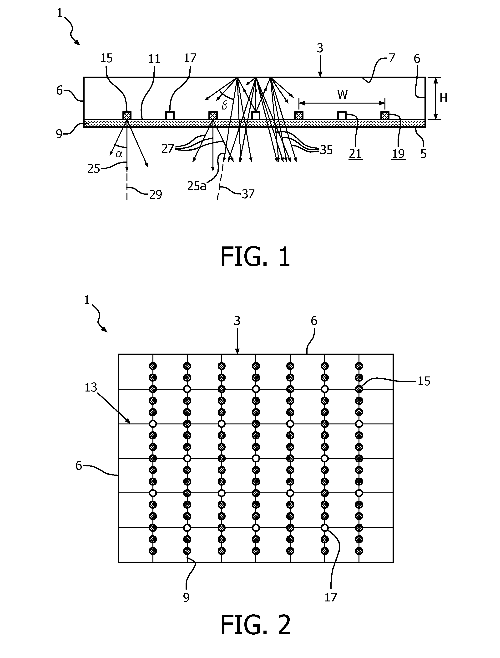
[0026]FIG. 1 shows a cross-sectional view of the lighting device 1 according to the invention. The lighting device comprises a housing 3 of height H, which housing comprises a light emission window 5 and, opposite thereto, a semi-specular reflective wall as a reflector 7, connected to each other by side walls 6. A planar carrier 9, in the figure a light transmissive, light diffusing plate, which is arranged in between the light emission window and the reflector, has, on a side 11 facing the reflector, a grid 13 (see FIG. 2) of alternating first 15 and second light sources 17 forming a first group 19 and a second group of light sources 21, respectively. The first light sources have a relatively small optical distance to the plate 9, whereas the second light sources, whose light is reflected by a white scattering layer with reflection coefficient of 0.9-1.0 have a relatively large optical distance to said plate. The diffuser is used to make discrete light sources and the grid less vis...

second embodiment

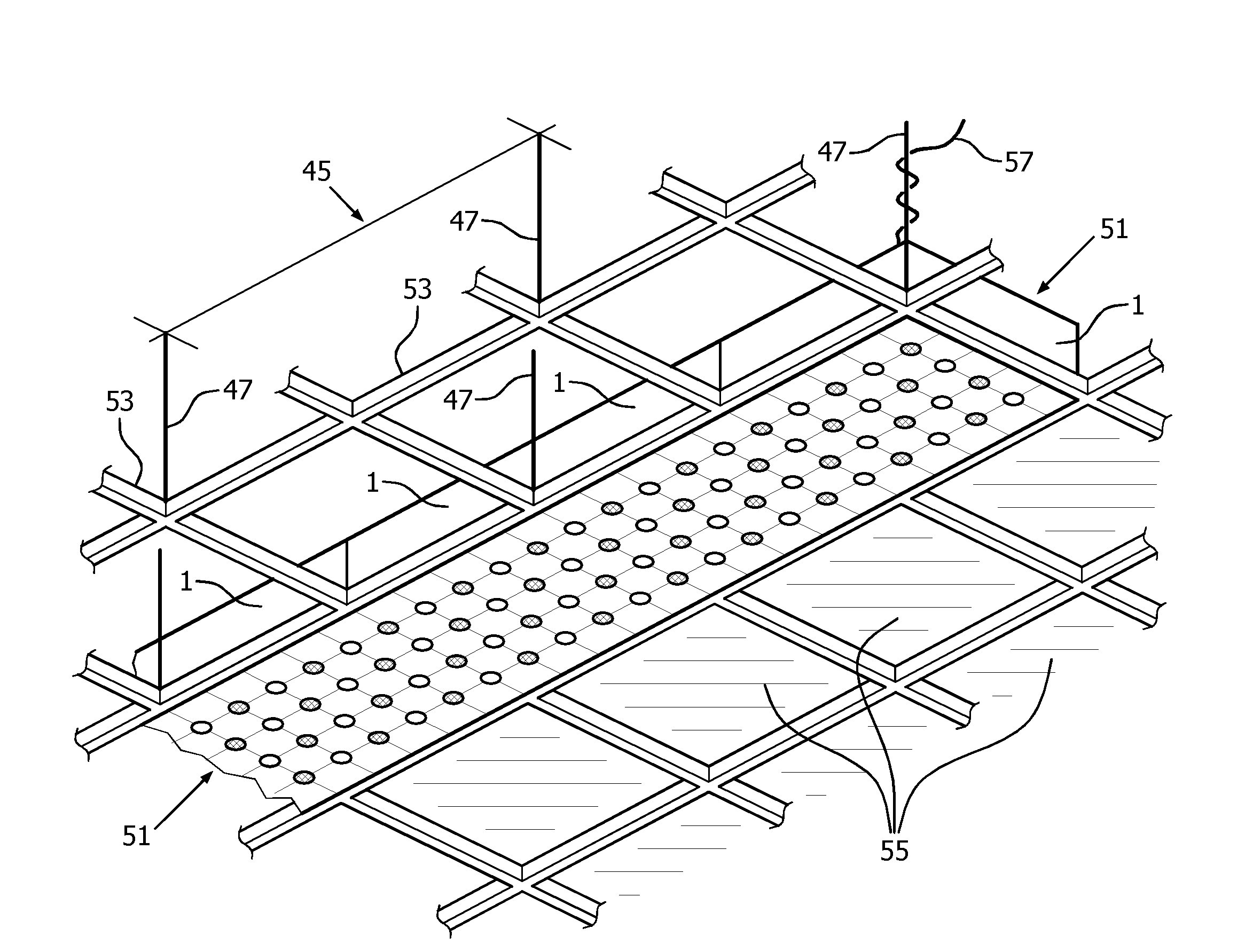
[0027]FIG. 2 shows a bottom view of the lighting device 1 according to the invention. The carrier 9 is an open frame provided with a grid 13 of first 15 and second 17 light sources, the carrier is fixed to walls 6 of the housing 3. The light sources are dimmable, color tunable LEDs in the figure, but the light sources alternatively could be dimmable miniature halogen lamps. The first light sources are arranged in lines (parallel or randomly oriented), such that the LEDs within a line are much closer, at least 3 times closer, than those between the lines. The first and second light sources are provided in a ratio of 3:1, causing R1 to be about 3, i.e. to be in the favorable range of 21<=4. The alternating arrangement of the first and second light sources is adapted to said ratio.

third embodiment

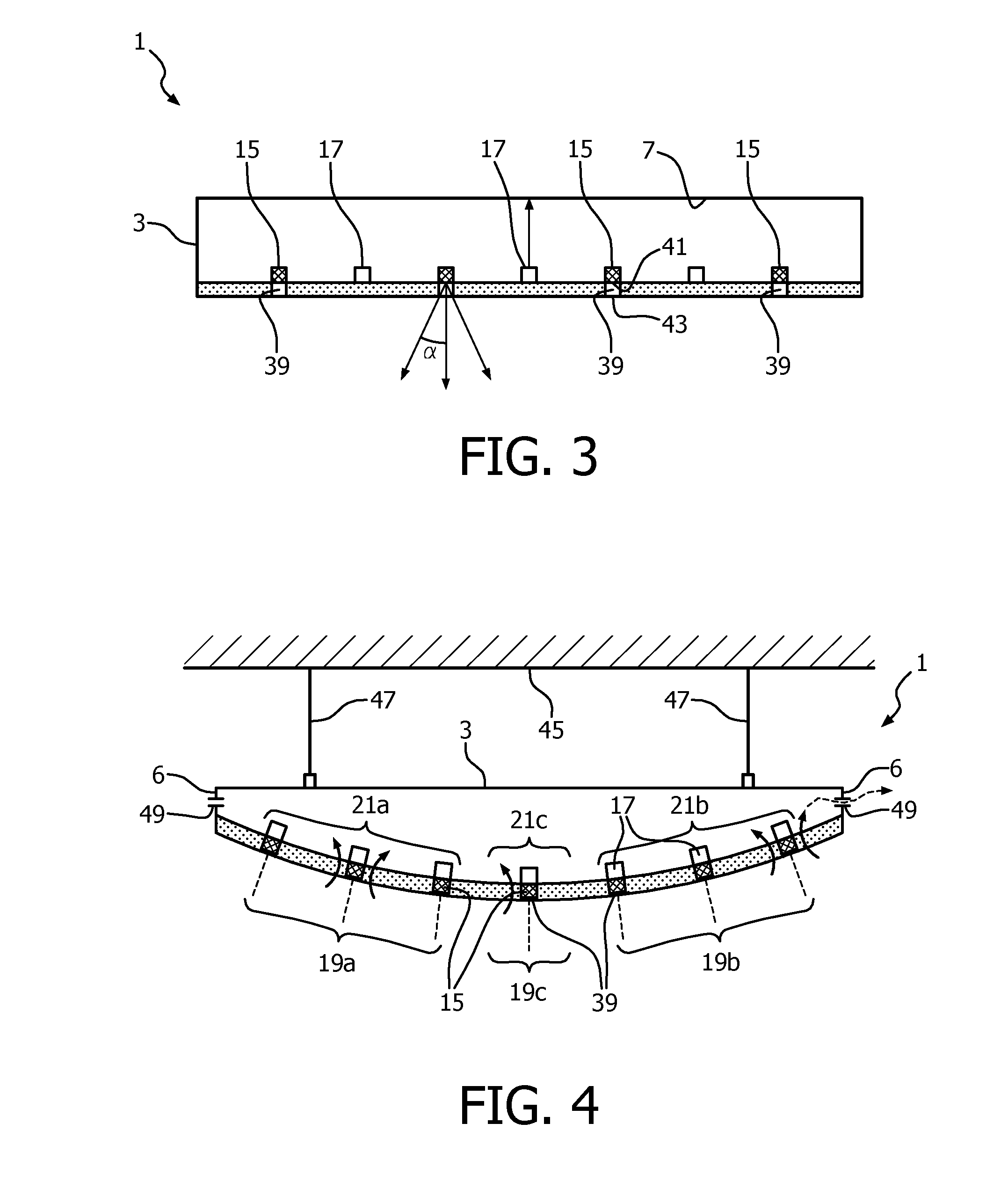
[0028]FIG. 3 shows a cross-sectional view of the lighting device 1 according to the invention, in which the first 15 and second light sources 17 are alternately arranged, similar to the embodiment shown in FIG. 1. In the embodiment of FIG. 3, the light-diffusing carrier plate 9, for example made of translucent PMMA, is provided with openings 39 for collimator light, with the first light sources 15 being located at a respective first end 41 facing the reflector 7 of a respective opening. The quality of the accent lighting is improved thereby, as the light beams of the first light sources issued at a respective second end 43 of the opening are more collimated and less diffused, i.e. beam angle α is relatively very small, for example 12° or less. Furthermore, less light from the first light sources is scattered back into the housing 3, so that the efficiency of the lighting device is increased.


PUM


Abstract

A lighting device (1) comprising a housing (3) with a light emission window (5) and, opposite thereto, a reflector (7). A planar light transmissive carrier (9) arranged in between the light emission window and the reflector and comprising, at least on a side (11) facing towards the reflector, a grid (13) of a plurality of light sources (15,17). The plurality of light sources comprise a first group (19) of first light sources (15) and a second group (21) of second light sources (19). Each first light source has a respective first emission orientation (23) in a respective first direction (25) away from the reflector and each second light source has a respective second emission orientation (31) to issue light towards the reflector, which light, after reflection, is redirected into a respective first direction (25a). The lighting device is able to provide accent lighting and / or diffuse lighting issued by light sources arranged on one planar carrier.

Description

TECHNICAL FIELD[0001]The invention relates to a lighting device comprising a housing comprising a light emission window and, opposite thereto, a reflector. The invention further relates to a lighting system comprising lighting devices.BACKGROUND OF THE INVENTION[0002]Such a lighting device is known from WO2009087587. The known lighting device comprises a light guide having a first and a second surface facing each other. The known lighting device further comprises light sources arranged to issue light source light in one direction. To shape light source light and provide shaped light, the known lighting device further comprises light shaping means, wherein the light shaping means is disposed at at least one of said surfaces. In the known lighting system the first surface is capable of providing light in the first direction and the second surface is capable of providing light in a second direction, the second direction being different from the first direction. In this manner, the know...

Claims


Application Information

Patent Timeline
Patent Type & Authority Applications(United States)
IPC IPC(8): F21V7/00F21V14/00F21S8/02
CPCF21V7/0016F21S8/026F21Y2113/005F21Y2105/003F21V14/003F21S8/061E04B9/006F21V5/00F21V33/006F21Y2105/10F21Y2105/12F21Y2105/16F21Y2107/50F21Y2109/00F21Y2113/13F21Y2115/10F21S8/04F21V2200/20G02B3/0056
Inventor BAAIJENS, JOHANNES PETRUS WILHELMUSSEKULOVSKI, DRAGAN
Owner SIGNIFY HLDG BV
Why Eureka
Try Eureka