Microfluidic tissue model

a microfluidic tissue and microfluidic technology, applied in the field of microfluidic tissue models, can solve the problems of manual placement of sensors affecting readings, artifacts in recordings,

Active Publication Date: 2015-10-22
CHARLES STARK DRAPER LABORATORY
View PDF6 Cites 17 Cited by
  • Summary
  • Abstract
  • Description
  • Claims
  • Application Information

AI Technical Summary

Benefits of technology

[0008]In some implementations, the method also includes measuring a velocity of a fluid flow in at least one of the first graduated microfluidic channel and the second graduated microfluidic channel. Measuring the velocity of the fluid flow includes measuring a movement of an air-fluid interface in at least one of the first graduated microfluidic

Problems solved by technology

To measure cellular properties of the modeled tissues, culture systems use external monitoring devices, which are disadvantageous because the electrodes and other sensors are manually placed in position and the culture devices must

Method used


Image

  • Microfluidic tissue model
  • Microfluidic tissue model
  • Microfluidic tissue model

Examples


Embodiment Construction

[0021]The various concepts introduced above and discussed in greater detail below may be implemented in any of numerous ways, as the described concepts are not limited to any particular manner of implementation. Examples of specific implementations and applications are provided primarily for illustrative purposes.

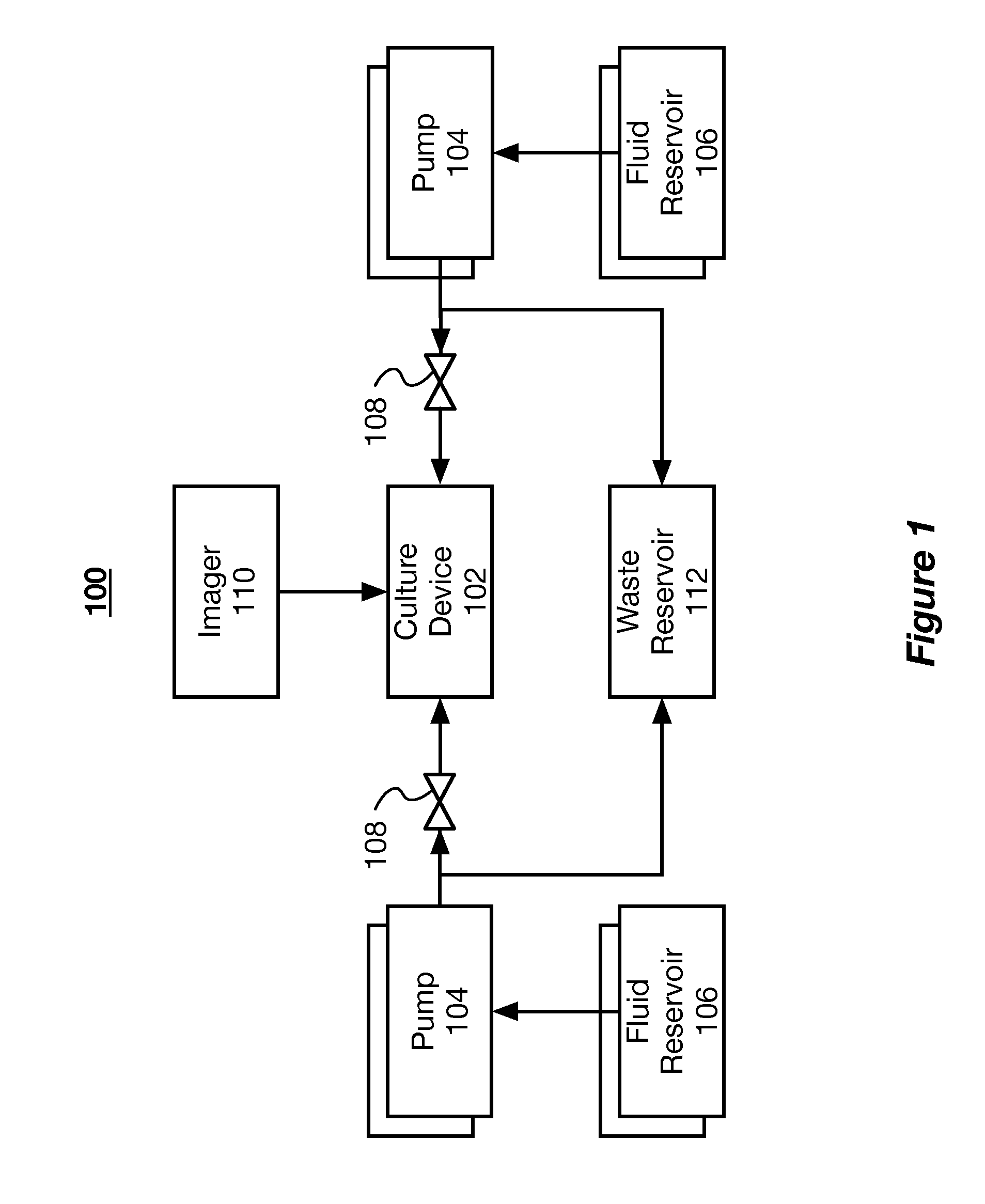
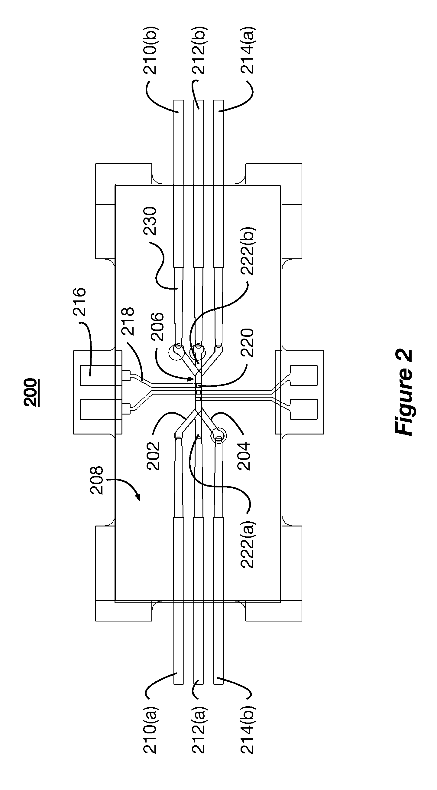
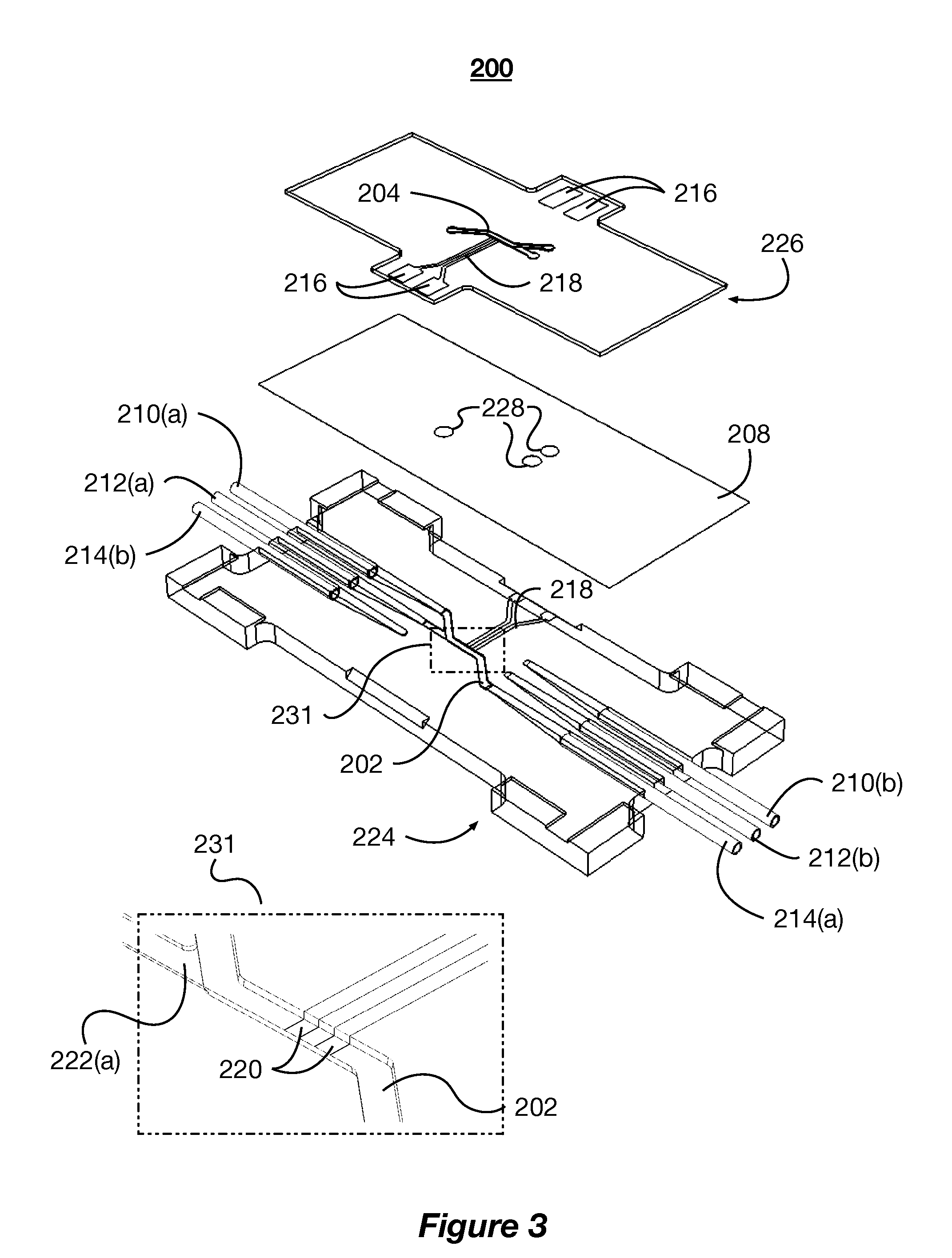
[0022]The present disclosure describes systems and methods for mimicking body tissue and the function thereof. The mimicked body tissue can include kidney tissue, the blood brain barrier, lung tissue, gastro-intestinal tissue, skin tissue, and other tissues. In some implementations, the systems described herein are used to test the impact of controlled factors on the tissue. The controlled factors can include flow rates, shear rates, topographical patterns, and test chemicals (e.g., therapeutics and toxins). In some implementations, the system and methods are used to test pharmaceutical and biological therapies, characterize healthy or diseased tissue, and observe phenomena...


PUM


Abstract

The present disclosure describes systems and methods for mimicking body tissue and the function thereof. The mimicked body tissue can include kidney tissue, the blood brain barrier, and other tissues. In some implementations, the systems described herein are used to test the impact of controlled factors on the tissue. The controlled factors can include flow rates, shear rates, and test chemicals (e.g., therapeutics and toxins). In some implementations, the system and methods are used to test pharmaceutical and biological therapies, characterize healthy or diseased tissue, and observe phenomena of the tissue in vitro.

Description

CROSS-REFERENCE TO RELATED APPLICATIONS[0001]This application claims priority to U.S. Provisional Patent Application No. 61 / 980,398 filed on Apr. 16, 2014 and titled “Microfluidic Tissue Model,” which is herein incorporated by reference in its entirety.BACKGROUND[0002]The modeling of tissue barriers, such as those formed by epithelial and endothelial cells in the vessels of the kidney and the blood brain barrier, is important for the development of pharmaceutical and other therapies. To measure cellular properties of the modeled tissues, culture systems use external monitoring devices, which are disadvantageous because the electrodes and other sensors are manually placed in position and the culture devices must be handled and removed from incubation to be measured. The manual placement of the sensors can affect readings if inconsistently placed. Also, placement of the sensors disturbs the tissue, which results in artifacts in the recordings.SUMMARY OF THE DISCLOSURE[0003]According t...

Claims


Application Information

Patent Timeline
IPC IPC(8): G01N33/50
CPCG01N33/5023C12M23/16C12M41/00C12M41/36
Inventor CHAREST, JOSEPH L.FROHLICH, ELSEDIBIASIO, CHRISTOPHERVANDEVOORDT, KENNETH
Owner CHARLES STARK DRAPER LABORATORY
Why Eureka
Try Eureka