Plasma reactor and plasma ignition method using the same

a plasma reactor and ignition method technology, applied in the direction of plasma technique, electric discharge lamps, electric lighting sources, etc., can solve the problems of increased process time, increased cost due to re-ignition, and failure of plasma discharge, so as to achieve easy plasma discharge and maintain the generated plasma. , the effect of minimizing damage to the plasma reactor

Inactive Publication Date: 2015-10-22
NEW POWER PLASMA CO LTD
View PDF10 Cites 70 Cited by
  • Summary
  • Abstract
  • Description
  • Claims
  • Application Information

AI Technical Summary

Benefits of technology

[0017]It is another object of the present invention to provide a plasma reactor capable of easily achieving plasma discharge and easily maintaining the generated plasma, as compared to conventional cases, even when the same voltage as that of conventional cases is supplied, and a plasma ignition method using the plasma reactor.
[0018]It is another object of the present invention to provide a plasma reactor capable of achieving plasma discharge even when a relatively low voltage is supplied, as compared to conventional cases, thereby enabling supply of an inexpensive product while minimizing damage to the plasma reactor caused by arc discharge, and a plasma ignition method using the plasma reactor.
[0019]It is another object of the present invention to provide a plasma reactor capable of easily achieving ignition for plasma discharge, as compared to conventional cases, even when the same voltage as that of conventional cases is supplied at a low gas flow rate and a low gas pressure, and a plasma ignition method using the plasma reactor.
[0020]It is a further object of the present invention to provide a plasma reactor capable of easily achieving ignition for plasma discharge, as compared to conventional cases, even when the same voltage as that of conventional cases is supplied at a low temperature, and a plasma ignition method using the plasma reactor.

Problems solved by technology

However, when a high voltage of, for example, 500V, is applied to the interior of the plasma chamber 4 maintained at a low atmospheric pressure of, for example, 3 torr, ignition failure may occur at a rate of 2 to 3 times per 1,000 times. When ignition failure occurs, it is necessary to perform a task for re-ignition and, as such, process time is increased.
Furthermore, costs are increased due to re-ignition.
The interior of the plasma chamber 4 may also be damaged due to arc discharge.
In addition, the insulator of the plasma reactor may be easily damaged or broken due to plasma generated in the plasma chamber 4.

Method used


Image

  • Plasma reactor and plasma ignition method using the same
  • Plasma reactor and plasma ignition method using the same
  • Plasma reactor and plasma ignition method using the same

Examples


first embodiment

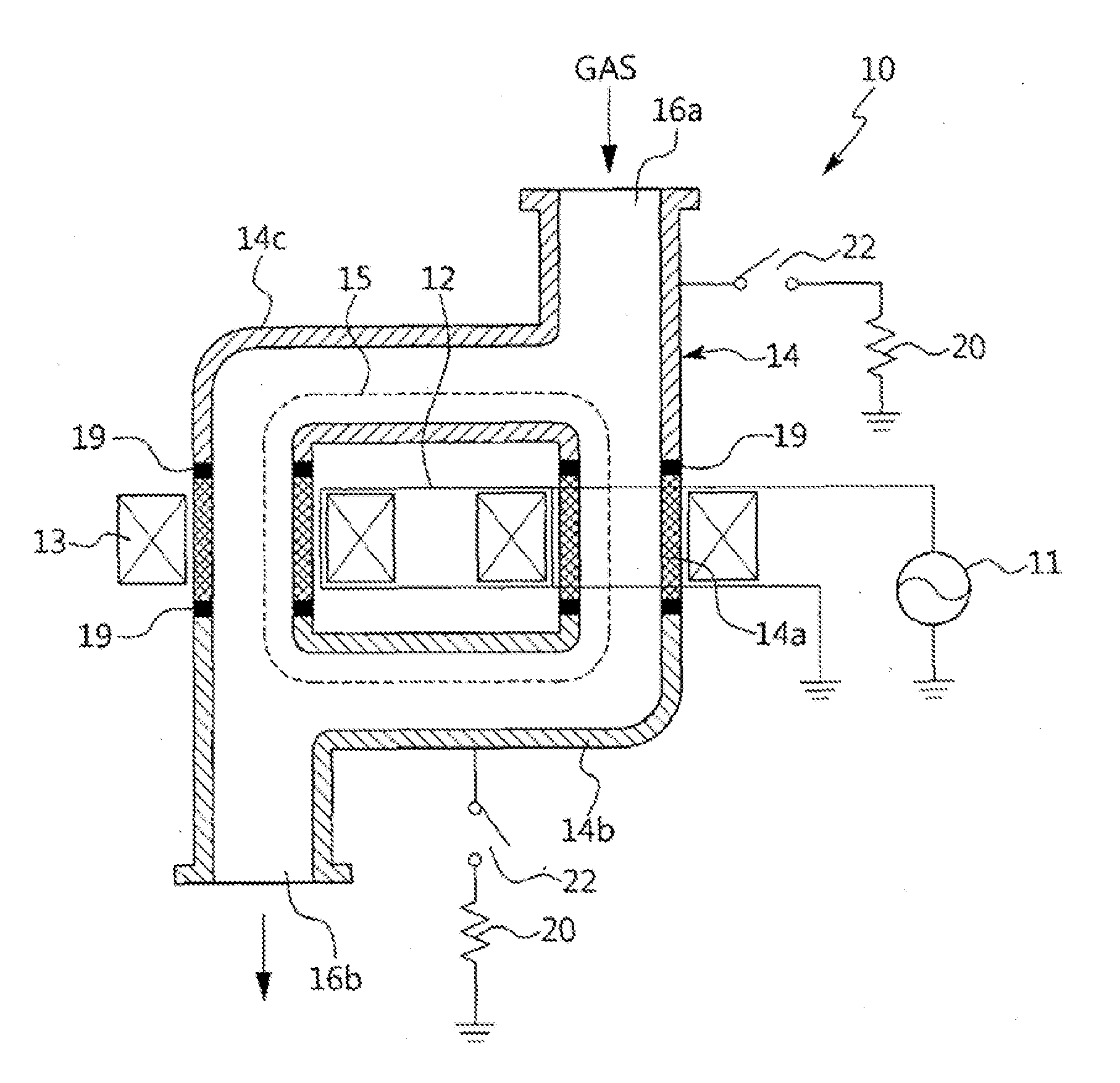
[0079]FIG. 4 is a view illustrating a transformer coupled plasma (TCP) / inductively coupled plasma (ICP) plasma reactor according to the present invention.

[0080]Referring to FIG. 4, the plasma reactor, which is designated by reference numeral “10”, includes a plasma chamber body 14a, first and second floating chambers 14b and 14c, a magnetic core 13, and an AC power supply 11. In the embodiment of the present invention, the plasma reactor 10 is a TCP type remote plasma generator.

[0081]The plasma reactor 10 has a discharge space for plasma discharge defined therein. The plasma reactor 10 includes a gas inlet 16a and a gas outlet 16b. The gas inlet 16a is connected to a gas supply source to supply a process gas for plasma discharge. The process gas supplied from the gas supply source is introduced into the reactor body 14 through the gas inlet 16b. The gas outlet 16b is connected to a process chamber (not shown). Plasma generated in the plasma reactor 10 is supplied to the process cham...

second embodiment

[0089]FIG. 5 is a view explaining a TCP / ICP coupled plasma reactor according to the present invention.

[0090]Referring to FIG. 5, the plasma reactor, which is designated by reference numeral “10a”, includes a plasma chamber body 14a, at which a magnetic core 13 is installed, and a plurality of floating chambers 14b, 14c, 14d, 14e, 14f, and 14g. Each of the plural floating chambers 14b, 14c, lid, 14e, 14f, and 14g is insulated from the plasma chamber body 14a and the remaining floating chambers. A voltage directly induced in the plasma chamber body 14a through the magnetic core 13 is indirectly transferred to third, fourth, fifth, and sixth ones of the floating chambers, namely, the floating chambers- 14d, 14e, 14f, and 14g. The transferred voltage is then, transferred to first and second ones of the floating chambers, namely, the floating chambers 14a and 14b. Each of the first to sixth floating chambers 14b to 14g are connected to a high resistor 20 by a switching circuit 22.

[0091]F...

sixth embodiment

[0095]FIG. 9 is a view explaining a TCP / ICP coupled plasma reactor according to the present invention.

[0096]Referring to FIG. 9, the plasma reactor, which is designated by reference numeral “10e”, includes a plurality of insulating regions 19 symmetrically formed at a reactor body 14, to separate a plasma chamber body 14a and a plurality of floating chambers. The plasma chamber body 14a, at which a magnetic core 13 is installed, is connected to first and second floating chambers 14b and 14c by insulating regions IS while being connected to third and fifth floating chambers 14d. and 14f by insulating regions 19. A sixth floating chamber 14g, which is arranged at a position crossing the plasma chamber body 14a, is connected to the second and fifth floating chambers 14c and 14f by insulating regions 19. A fourth floating chamber 14e is connected to the first and third floating chambers 14b and 14d by insulating regions 19. Thus, the first to sixth floating chambers 14b to 14g are insul...


PUM


Abstract

A plasma reactor and a plasma ignition method using the same are disclosed. The disclosed plasma reactor includes at least one magnetic core having a transformer primary winding wound thereon, an AC power supply for supplying AC power to the transformer primary winding wound on the magnetic core, at least one plasma chamber body, at which the magnetic core is installed, to directly induce a voltage in the plasma chamber body through the magnetic core, thereby inducing induced electromotive force in the plasma chamber body, and at least one floating chamber connected to the plasma chamber body via an insulating region, the induced electromotive force from the plasma chamber body being indirectly transferred to the floating chamber. Ignition of plasma is generated in accordance with a voltage difference generated between, the plasma chamber body and the floating chamber, and the ignited plasma is supplied to a process chamber.

Description

BACKGROUND OF THE INVENTION[0001]1. Field of the Invention[0002]The present invention relates to a plasma reactor and a plasma ignition method using the same, and more particularly to a plasma reactor capable of achieving plasma discharge even when a relatively low voltage is supplied in a transformer coupled plasma (TCP) or inductively coupled plasma (1CP) source system, as compared to conventional cases, and alleviating plasma discharge conditions while being advantageous in terms of maintenance or continuance of plasma after initiation of plasma discharge when the same voltage as that of conventional cases is supplied, as compared to conventional cases, and a plasma ignition method using the plasma reactor.[0003]2. Description of the Related Art[0004]Plasma means a gas state in which electrons having negative charges and ions having positive charges are separated from each other at an ultrahigh temperature. In this state, the resultant gas, namely, plasma, exhibits neutrality bec...

Claims


Application Information

Patent Timeline
Patent Type & Authority Applications(United States)
IPC IPC(8): H01J37/32
CPCH01J37/321H01J2237/327H01J37/32458H05H1/46H01J37/32467H05H1/4652
Inventor CHOI, SANG-DON
Owner NEW POWER PLASMA CO LTD
Why Eureka
Try Eureka