Wrap-around micro-wire circuit method

a micro-wire circuit and wire wrapping technology, applied in the field of transparent electrodes, can solve the problems of limited transparency and conductivity, tendency to crack under mechanical or environmental stress, and increasing cost of transparent conductive metal oxides, and achieve the effects of improving connectivity, computing capability, transparency and manufacturability, and reducing the number of parts and manufacturing steps

Inactive Publication Date: 2015-10-22
EASTMAN KODAK CO
View PDF1 Cites 15 Cited by
  • Summary
  • Abstract
  • Description
  • Claims
  • Application Information

AI Technical Summary

Benefits of technology

[0020]The present invention provides micro-wire structures with improved connectivity, computing capability, transparency, and manufacturability. The micro-wire structures of the present invention are particularly useful in transparent touch screens or display devices. The integration of an electrode portion and a circui...

Problems solved by technology

Such conductive materials are well known in the display and touch-screen industries and have a number of disadvantages, including limited transparency and conductivity and a tendency to crack under mechanical or environmental stress.
Transparent conductive metal oxides are increasingly expensive and relatively costly to deposit and pattern.
Moreover, the substrate materials are limited by the electrode material deposition process (e.g. sputtering) and the current...

Method used


Image

  • Wrap-around micro-wire circuit method
  • Wrap-around micro-wire circuit method
  • Wrap-around micro-wire circuit method

Examples


Embodiment Construction

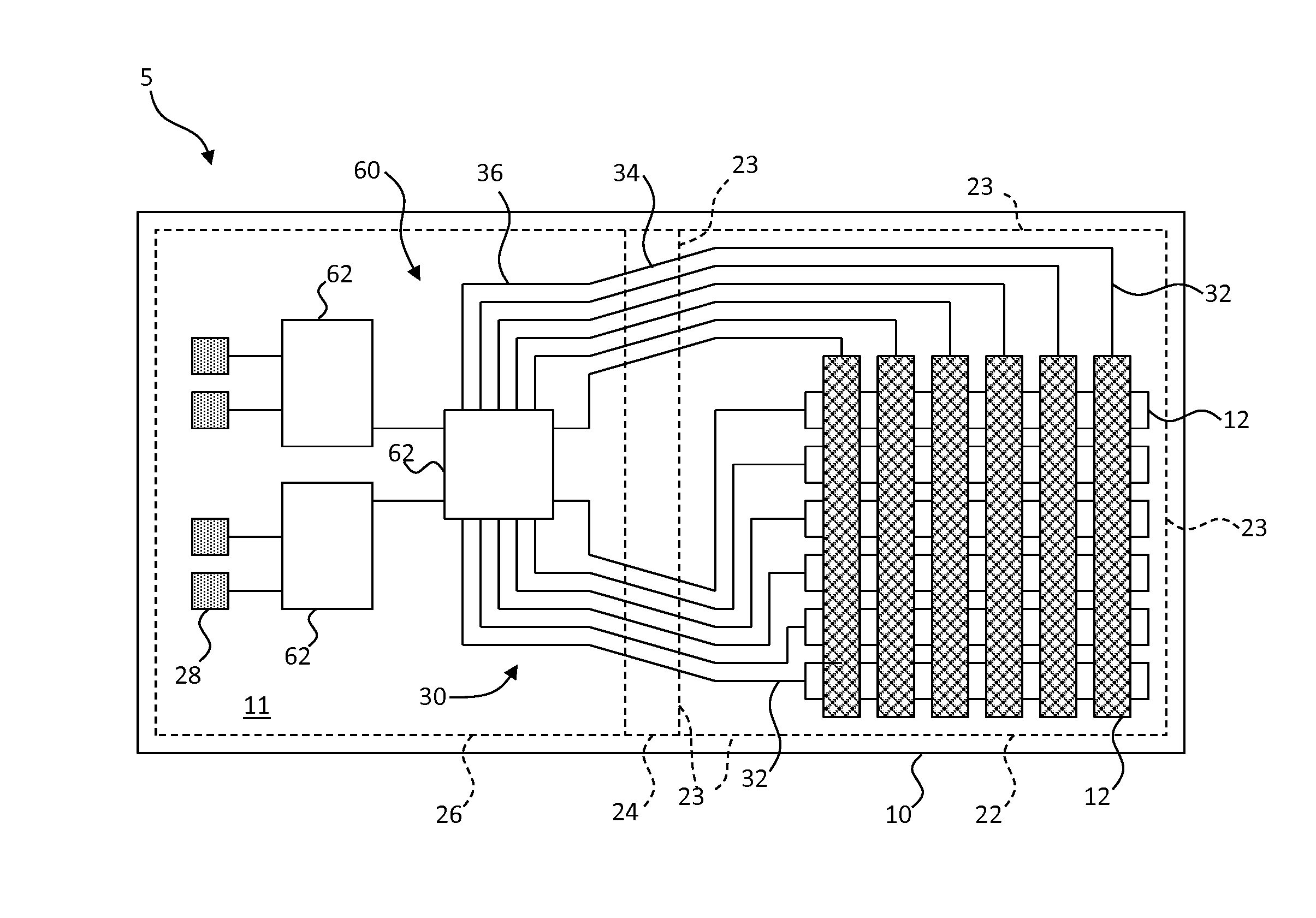
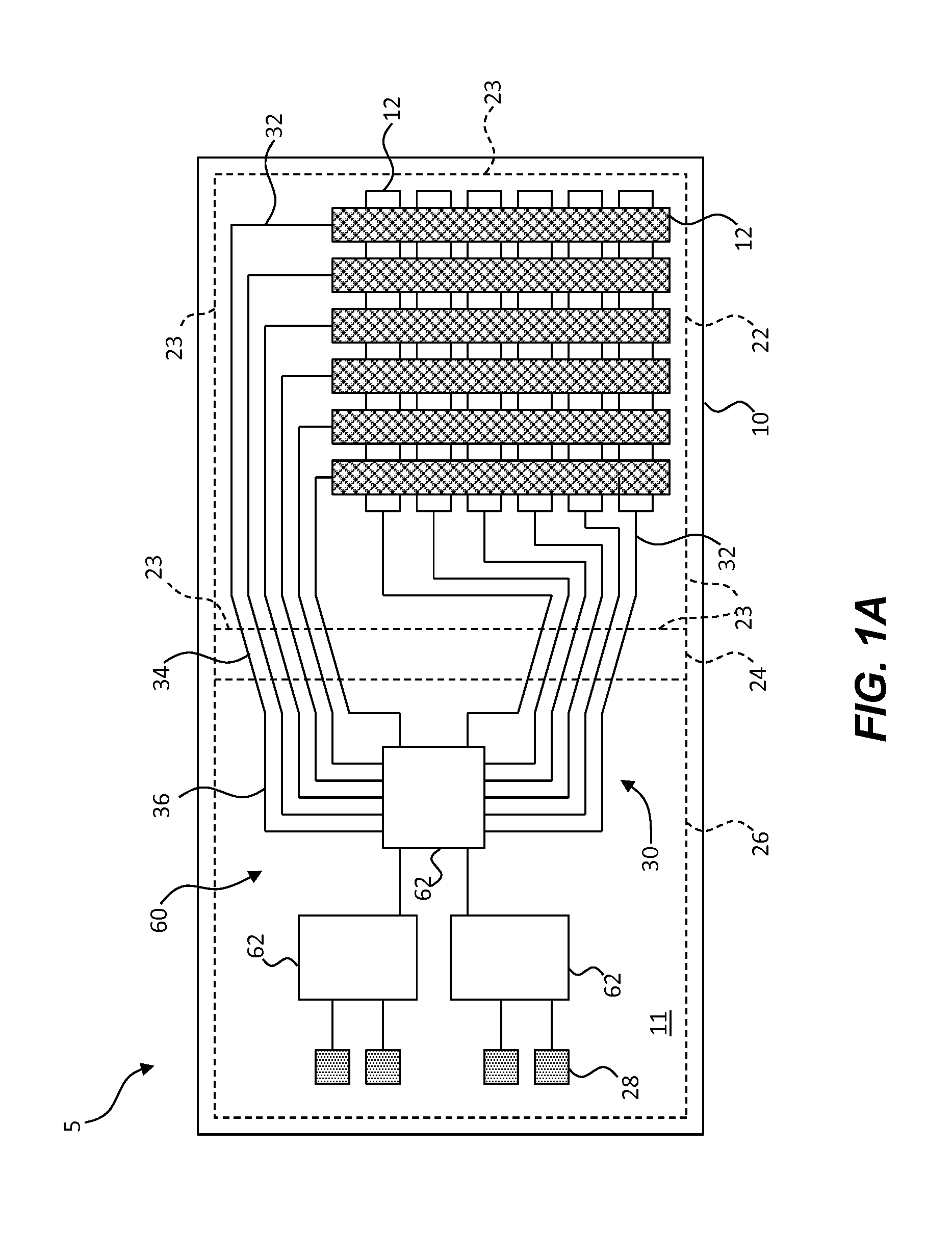
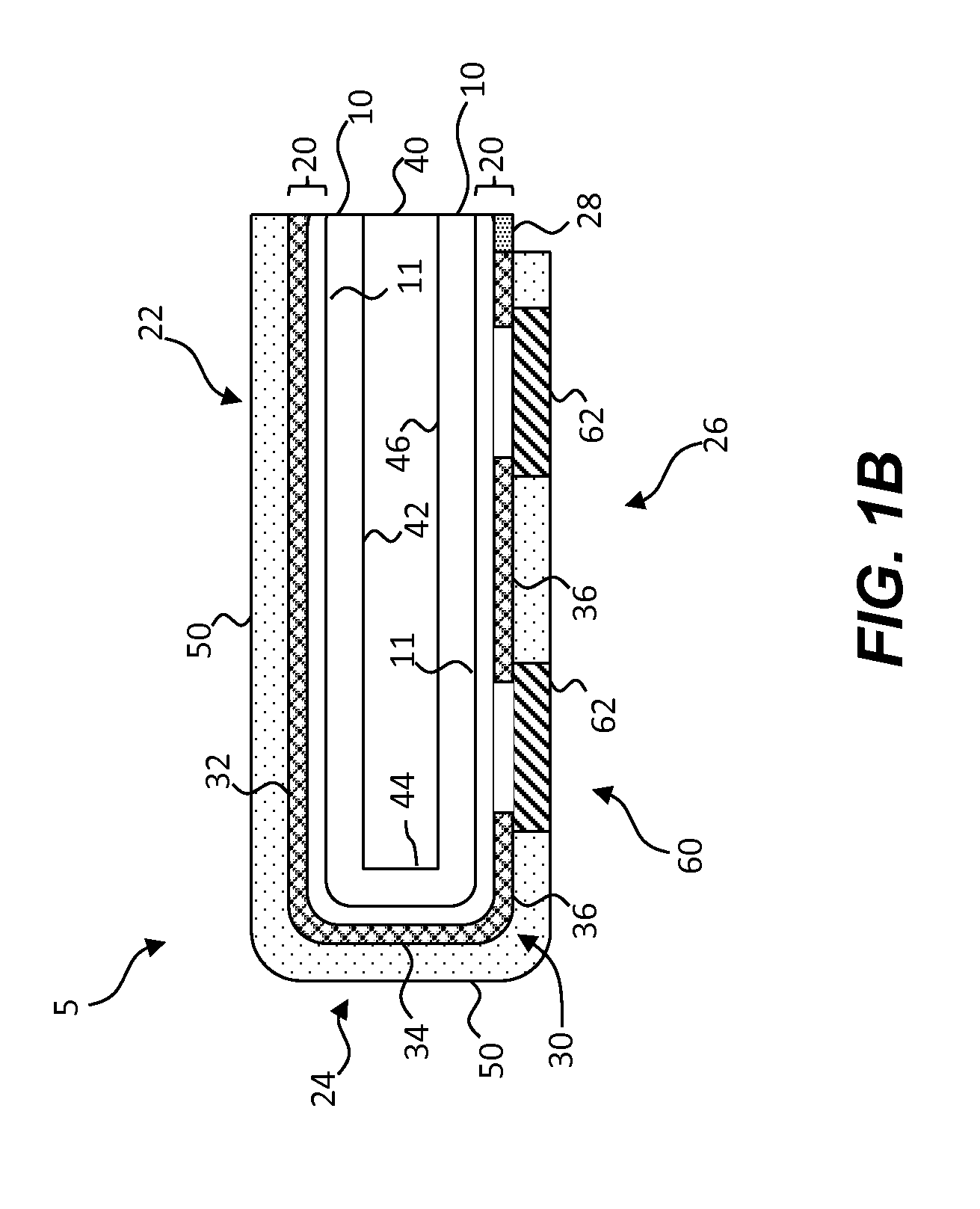
[0035]The present invention is directed toward a micro-wire circuit structure adapted for wrapping. The micro-wire circuit structure includes a single flexible substrate having both apparently transparent micro-wire electrodes and an electronic circuit for controlling the transparent micro-wire electrodes on a common side of the flexible substrate. The single flexible substrate is wrapped around a display so that a portion of the flexible substrate having the transparent electrodes is located adjacent to a viewing side of a display and a portion of the flexible substrate having the electronic circuit is located on a back side of the display opposite the viewing side.

[0036]FIG. 1A is a plan view of a micro-wire circuit structure 5 in an unwrapped configuration according to an embodiment of the present invention. In FIG. 1B, according to another embodiment of the present invention, a corresponding cross section of the micro-wire circuit structure 5 includes a display 40 having a displ...


PUM

PropertyMeasurementUnit
Thicknessaaaaaaaaaa
Flexibilityaaaaaaaaaa

Abstract

A method of making a micro-wire circuit structure adapted for wrapping includes providing a display and a flexible substrate. The flexible substrate includes a plurality of electrically conductive micro-wires on, in, or adjacent to a common side of the flexible substrate and forming micro-wire electrodes in a touch portion of the flexible substrate. One or more electrical circuits is located on or in a circuit portion of the flexible substrate and one or more micro-wires electrically connects the one or more electrical circuits to corresponding micro-wire electrodes. The flexible substrate is located in relation to the display with the touch portion located adjacent to a display viewing side, the circuit portion located adjacent to a display back side, and an edge portion of the flexible substrate wrapping around a display edge from the display viewing side to the display back side.

Description

CROSS REFERENCE TO RELATED APPLICATIONS[0001]Reference is made to commonly-assigned, co-pending U.S. patent application Ser. No. ______ filed concurrently herewith, entitled “Wrap-Around Micro-Wire Circuit Structure” by Tombs et al and to commonly-assigned, co-pending U.S. patent application Ser. No. 14 / 217,539 filed Mar. 18, 2014 entitled “Making Multi-Layer Micro-Wire Structure” by Cok, and to commonly-assigned, co-pending U.S. patent application Ser. No. 14 / 012,150 filed Aug. 28, 2013 entitled “Imprinted Multi-Layer Micro-Structure Method” by Cok, the disclosures of which are incorporated herein.FIELD OF THE INVENTION[0002]The present invention relates to transparent electrodes having electrically conductive micro-wires and integrated circuits formed on a common flexible substrate.BACKGROUND OF THE INVENTION[0003]Transparent electrical conductors are widely used in the flat-panel display industry to form electrodes that are used to electrically switch light-emitting or light-tran...

Claims


Application Information

Patent Timeline
IPC IPC(8): H05K1/02H05K3/46H05K3/12H05K3/28H05K3/10
CPCH05K1/028H05K3/28H05K3/107H05K2201/056H05K3/4635H05K2203/0502H05K3/1258G06F3/04164G06F2203/04103H05K1/189H05K2201/0108H05K2201/055H05K2201/10128Y10T29/4913Y10T29/49156Y10T29/49158Y10T156/1015H05K1/0274H05K3/22H05K2201/10121
Inventor TOMBS, THOMAS NATHANIELCOK, RONALD STEVENMORTON, CHRISTOPHER R.
Owner EASTMAN KODAK CO
Why Eureka
Try Eureka