
Catheter With Inner Surface Pressure Sensor for Providing a Vascular Pressure Measurement for Determining Fractional Flow Reserve

a technology of vascular pressure measurement and catheter, which is applied in the field of catheter with inner surface pressure sensor for providing a vascular pressure measurement for determining fractional flow reserve, can solve the problems that conventional ffr wires are not desired by clinicians to be used as guide wires, and errors may be introduced into blood pressure measurement, and achieve accurate pressure measurement

Inactive Publication Date: 2015-10-29
MEDTRONIC VSACULAR GALWAY
View PDF1 Cites 23 Cited by
  • Summary
  • Abstract
  • Description
  • Claims
  • Application Information

AI Technical Summary

Benefits of technology

The measurement catheter described in this patent has a distal portion with a smaller outer diameter than the proximal portion, which allows for accurate pressure measurement in the vasculature. The catheter can track to a treatment site and have its distal guidewire lumen filled with blood, providing accurate pressure readings even with a guidewire in place. The catheter can also have a differential pressure sensor that senses the pressure difference between blood flowing distally past the sensor and blood at the distal end of the catheter. This allows for more accurate pressure readings and a better understanding of blood flow patterns in the vasculature.

Problems solved by technology

Conventional FFR wires generally are not desired by clinicians to be used as guide wires for such interventional devices.
Further, some error may be introduced into a blood pressure measurement taken distal of a lesion if a cross-sectional size of the portion of the measurement device that crosses the lesion is too large such that it acts to further restrict blood flow therethrough.

Method used


Image

  • Catheter With Inner Surface Pressure Sensor for Providing a Vascular Pressure Measurement for Determining Fractional Flow Reserve
  • Catheter With Inner Surface Pressure Sensor for Providing a Vascular Pressure Measurement for Determining Fractional Flow Reserve
  • Catheter With Inner Surface Pressure Sensor for Providing a Vascular Pressure Measurement for Determining Fractional Flow Reserve

Examples


Embodiment Construction

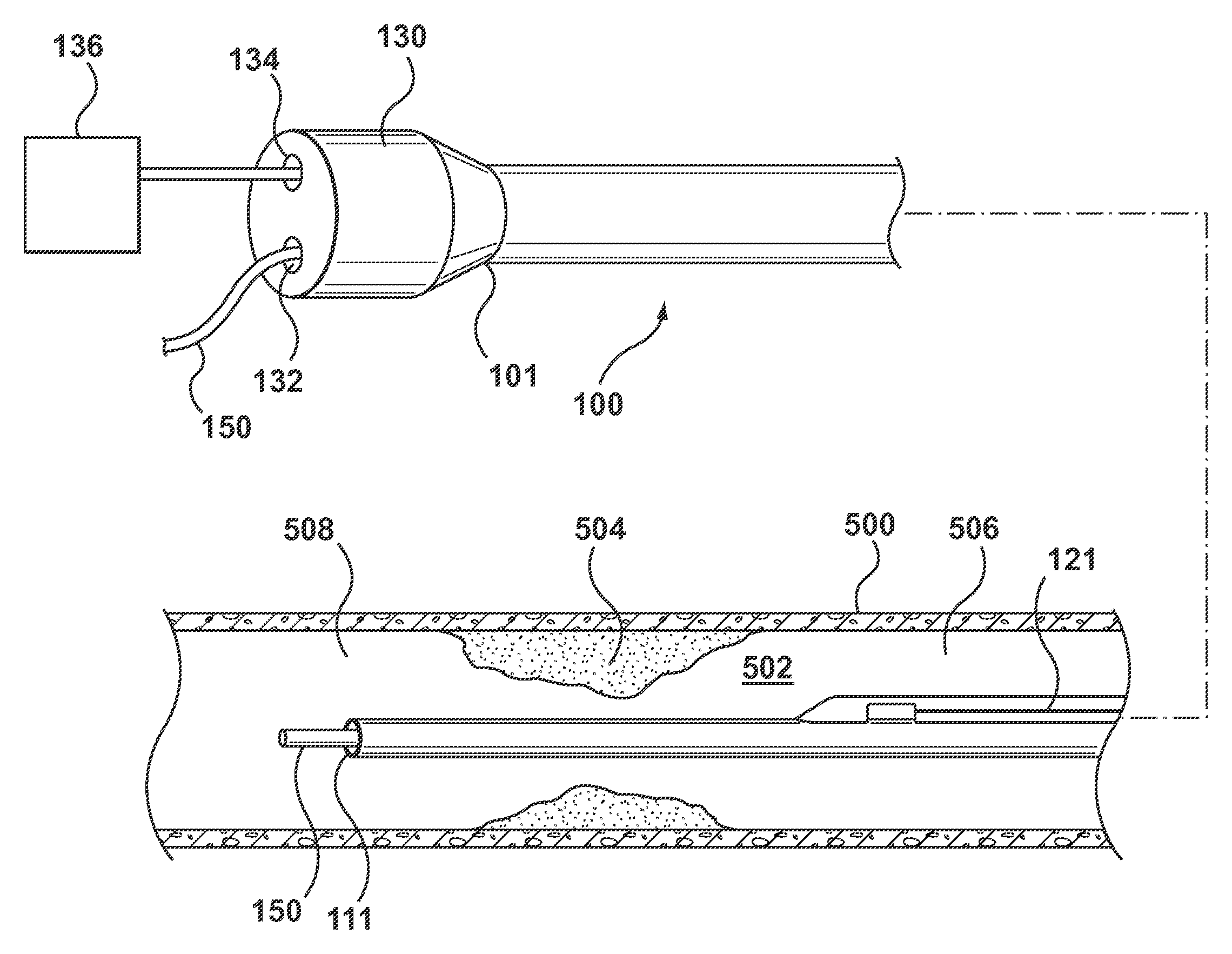
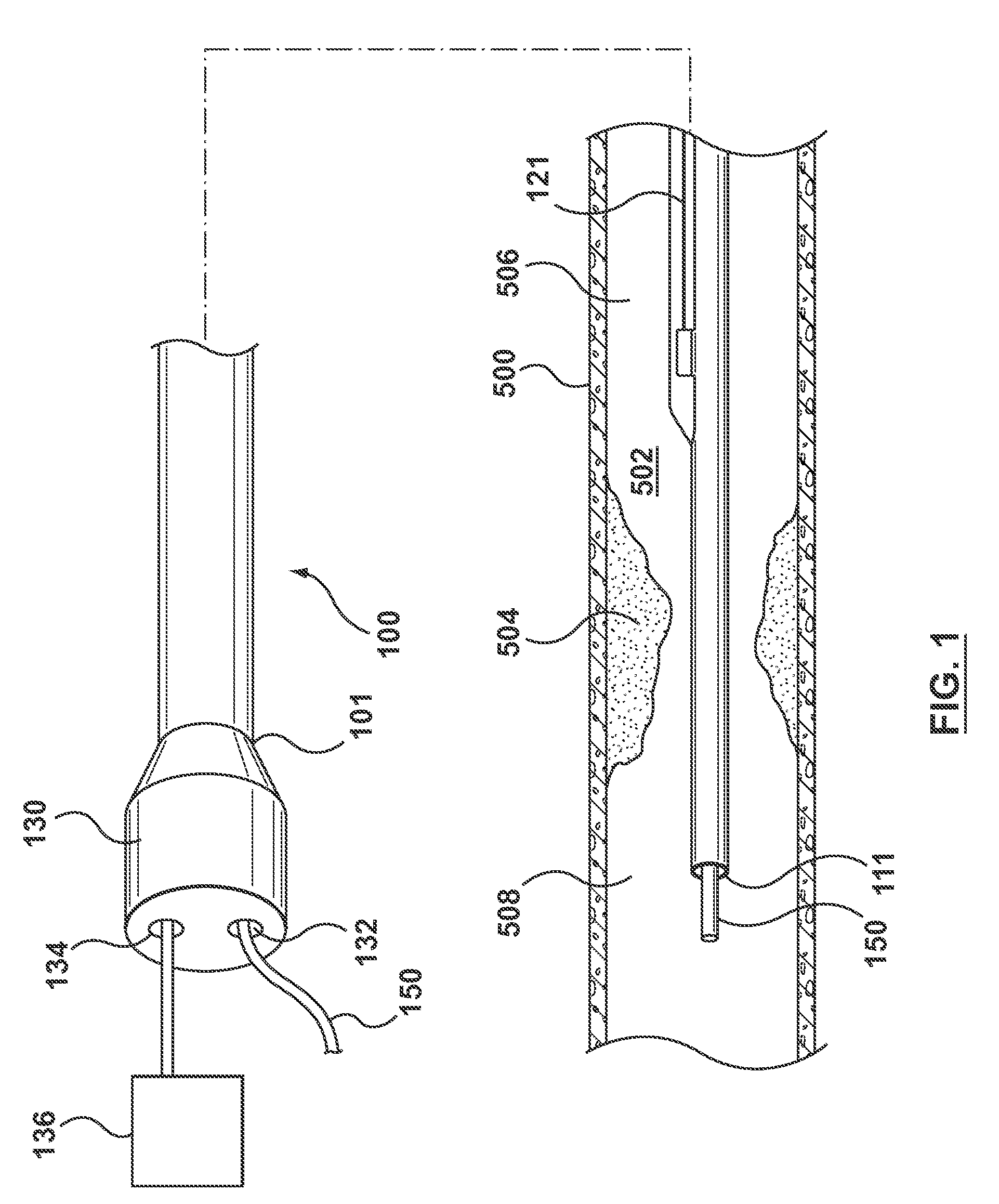
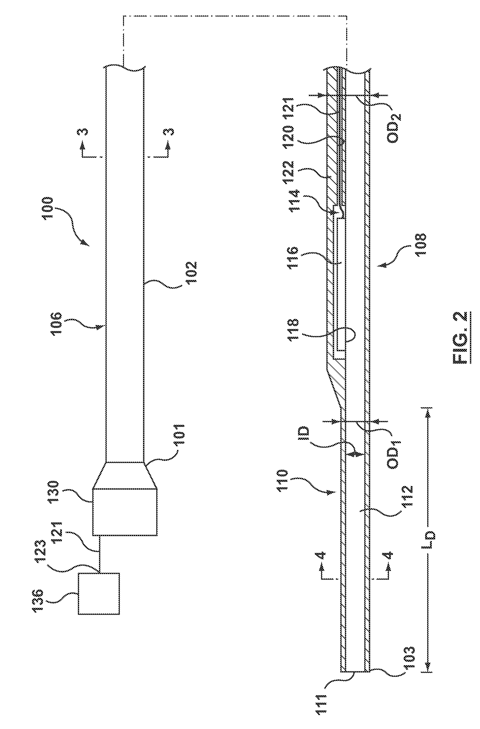
[0026]Specific embodiments of the present invention are now described with reference to the figures, wherein like reference numbers indicate identical or functionally similar elements. The terms “distal” and “proximal” are used in the following description with respect to a position or direction relative to the treating clinician. “Distal” and “distally” are positions distant from or in a direction away from the clinician. “Proximal” and “proximally” are positions near or in a direction toward the clinician.

[0027]The following detailed description is merely exemplary in nature and is not intended to limit the invention or the application and uses of the invention. Although the description of the invention is in the context of treatment of blood vessels such as the coronary arteries, the invention may also be used in any other body passageways where it is deemed useful such as but not limited to peripheral arteries, carotid arteries, renal arteries, and / or venous applications. Furthe...


PUM


Abstract

A catheter includes an elongate shaft including a proximal portion and a distal portion extending from the proximal portion to a distal opening at a distal end of the shaft. The proximal portion defines a proximal guidewire lumen and has a first outer diameter. The distal portion defines a distal guidewire lumen in communication with the proximal guidewire lumen and has a second outer diameter smaller than the first outer diameter. A pressure sensor is coupled to the proximal portion such that the pressure sensor faces the proximal guidewire lumen. When the catheter is tracked to a treatment site within the vasculature, the pressure sensor is disposed proximal the treatment site, the distal opening is disposed distal to the treatment site, and the distal guidewire lumen fills with blood such that the pressure sensor senses a pressure of the blood at the distal end of the shaft.

Description

FIELD OF THE INVENTION[0001]The invention methods and systems for determining a pressure gradient across a lesion of a vessel for calculating a Fractional Flow Reserve.BACKGROUND OF THE INVENTION[0002]The severity of a stenosis or lesion in a blood vessel may be assessed by obtaining proximal and distal pressure measurements relative to the given stenosis and using those measurements for calculating a value of the Fractional Flow Reserve (FFR). FFR is defined as the ratio of a first pressure measurement (Pd) taken on the distal side of the lesion and to a second pressure measurement taken on the proximal side of the lesion usually within the aorta (Pa). Conventionally, a sensor placed on the distal portion of a guidewire or FFR wire to obtain the first pressure measurement Pd, while an external pressure transducer is fluidly connected via tubing to a guide catheter for obtaining the second or aortic (AO) pressure measurement Pa. Calculation of the FFR value provides a lesion specifi...

Claims


Application Information

Patent Timeline
Patent Type & Authority Applications(United States)
IPC IPC(8): A61B5/0215A61M25/09A61B5/02
CPCA61B5/02158A61M2025/0002A61M25/09A61B5/02007A61B5/6852A61B5/0215A61B2562/0247
Inventor MCCAFFREY, GERRYSWEENEY, FIACHRAO'CONNELL, BARRYMURPHY, CHRISTOPHERWARD, SEAN
Owner MEDTRONIC VSACULAR GALWAY
Learn More