Method and device for controlling rotation angle of c-arm of medical imaging apparatus

Inactive Publication Date: 2015-10-29
CORELINE SOFT
View PDF5 Cites 12 Cited by
  • Summary
  • Abstract
  • Description
  • Claims
  • Application Information

AI Technical Summary

Benefits of technology

[0027]According to the present invention, it is possible to easily acquire an optimized medical image suitable for the diagnosis of a patient or a subject using a C-arm type medical imaging apparatus. That is, the present invention makes it possible to search for an optimal sliding rotation angle based on images taken using a C-arm type medical imaging apparatus.
[0028]According to the present invention, it is possible to acquire medical images while rotating a C-arm within the specific range of C-arm sliding rotation angles, to search for an optimal image candidate through the processing of the medical images and the analysis of the characteristics thereof, and to extract an optimal C-arm sl

Problems solved by technology

This is problematic in that the radiation expos

Method used


Image

  • Method and device for controlling rotation angle of c-arm of medical imaging apparatus
  • Method and device for controlling rotation angle of c-arm of medical imaging apparatus
  • Method and device for controlling rotation angle of c-arm of medical imaging apparatus

Examples


first embodiment

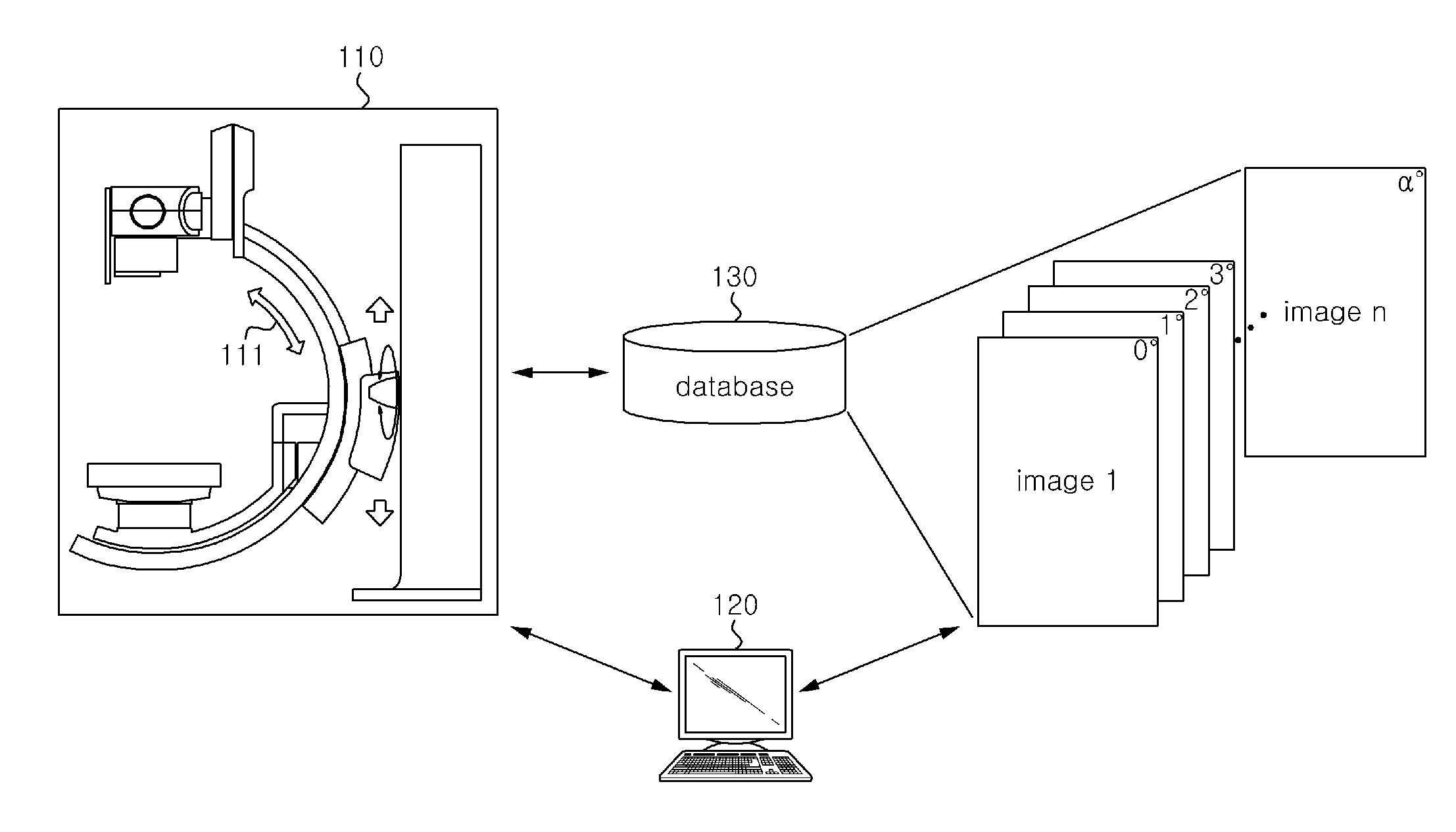
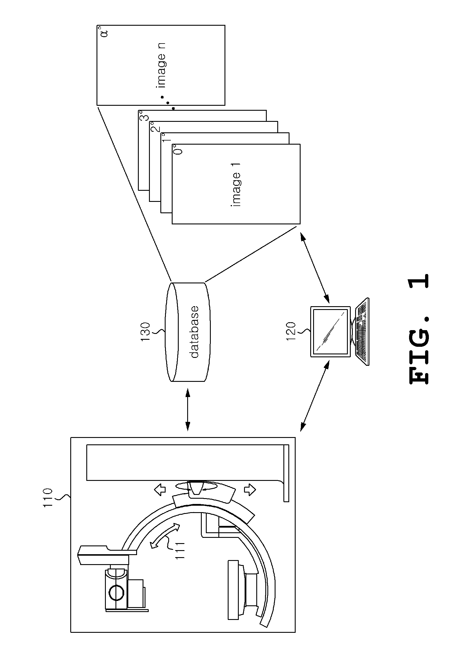
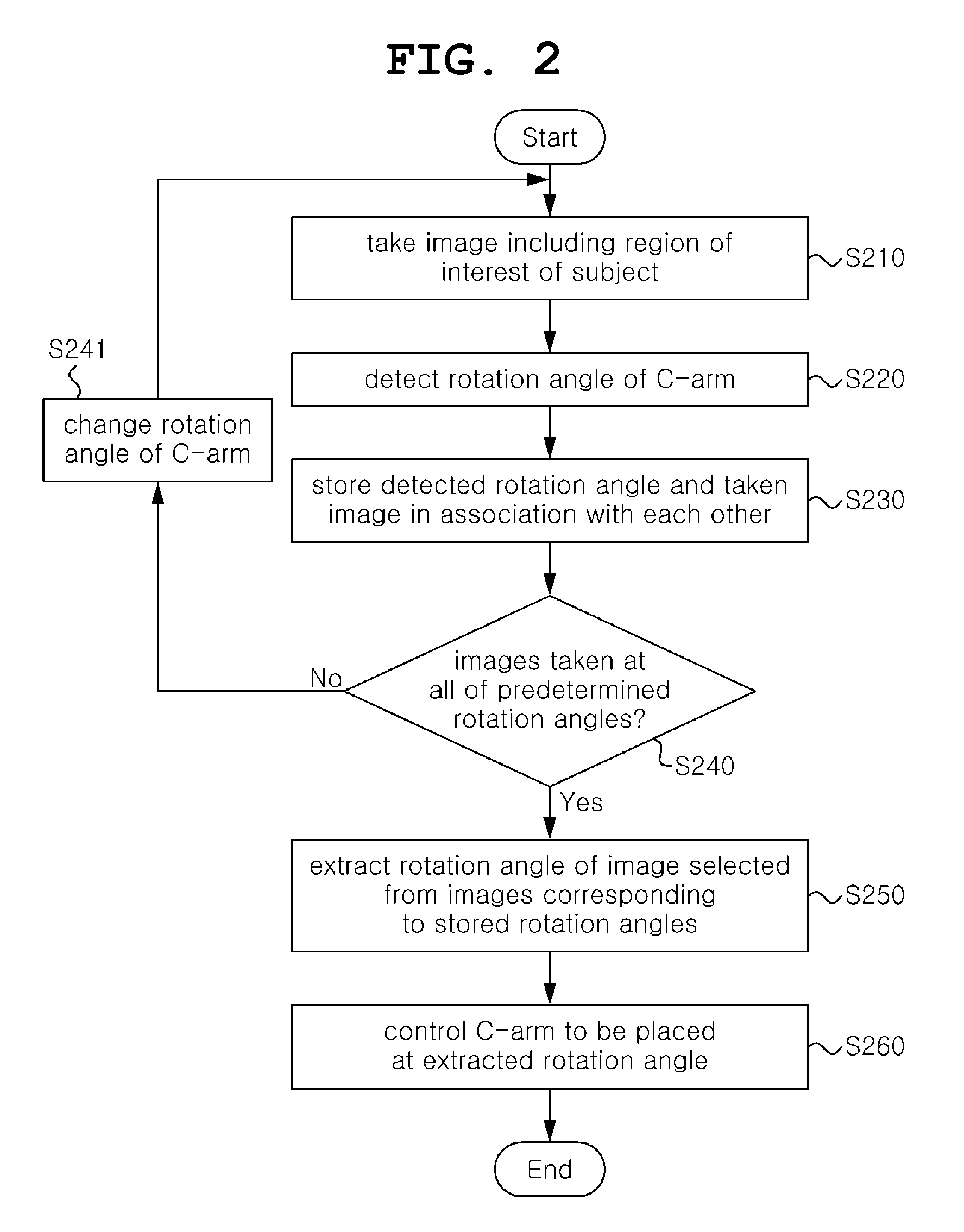
[0054]The range of the C-arm sliding rotation angles 111 within which the preliminary medical images will be taken may be manually input by a user (operator), or may be determined by the control device (processor) of the computing system 120 or medical imaging apparatus 110 in order to conform to the purpose of the diagnosis or medical treatment of a patient or a subject. For example, if it is considered to be most advantageous based on common sense to take an image from a location immediately above a patient or a subject when a needle is inserted into the patient or the subject for the purpose of biopsy, the C-arm sliding rotation angle 111 may be set within a specific range around 90 degrees, and preliminary medical images may be taken at regular intervals of 1 degree or at regular time intervals (e.g., at intervals of 1 or 0.1 sec). In this case, depending on the posture of a patient or a subject or the position of a biopsy target organ, a value other than 90 degrees, e.g., 88 de...

second embodiment

[0056]In the process of selecting an optimal present image candidate from preliminary medical images, the image processing module of the computing system 120 may detect an image, predetermined by a user, from fluoroscopy images in which a C-arm sliding rotation angle has been stored with respect to each frame. The image predetermined by a user may include a predetermined pattern, such as a surgical operation part of a subject (a patient), a hole formed for the insertion of a needle, an artifact, or the like. The image processing module of the computing system 120 may automatically detect an image, predetermined by a user, from fluoroscopy images in which a C-arm sliding rotation angle has been store with respect to each frame. The computing system 120 may provide a user with an image of a frame, from which a predetermined image is detected, more preferentially than images of other frames. The term “preferentially provide” means that an image is conspicuously displayed so that a user...


PUM


Abstract

A method and device for controlling a medical imaging apparatus are disclosed herein. The device for controlling a medical imaging apparatus includes a processor. The processor controls a medical imaging apparatus to take a plurality of images including a region of interest of a subject, while a C-arm of the medical imaging apparatus rotates from a first rotation angle to a second rotation angle. The processor detects the rotation angle of the C-arm of the medical imaging apparatus corresponding to each of the taken images. The processor stores the detected rotation angle in a database, along with the taken image. The processor extracts a rotation angle, stored along with an image selected as an optimal image from the taken images, as an optimal rotation angle.

Description

CROSS-REFERENCE TO RELATED APPLICATION[0001]This application claims under 35 U.S.C. §119(a) the benefit of Korean Application No. 10-2014-0050921 filed Apr. 28, 2014, which is incorporated herein by reference.TECHNICAL FIELD[0002]Embodiments of the present invention relate, in general, to a method and device for controlling the rotation angle of a C-arm of the medical imaging apparatus and, more particularly, to technology for searching for the rotation angle of a C-arm at which an optimal medical image can be acquired and controlling the C-arm so that the C-mm has an optimal rotation angle.BACKGROUND ART[0003]Different types of medical imaging and diagnosing apparatuses are used to diagnose affected parts of patients or subjects who visit hospitals. Among these apparatuses, an X-ray radiography apparatus is most widely used.[0004]In general, an X-ray imaging apparatus shows the differences in absorptivity between different internal organs of a human body using X-rays, the degree of...

Claims


Application Information

Patent Timeline
IPC IPC(8): A61B6/00
CPCA61B6/547A61B6/4441A61B6/463A61B6/465A61B6/469A61B6/12A61B6/467A61B6/487A61B6/5235A61B6/00A61B6/08
Inventor KIM, JIN KOOKWON, TAEK SEO
Owner CORELINE SOFT
Why Eureka
Try Eureka