
Floating structure for supporting a wind turbine

Active Publication Date: 2015-10-29
UNIV POLITECNICA DE CATALUNYA
View PDF0 Cites 8 Cited by
  • Summary
  • Abstract
  • Description
  • Claims
  • Application Information

AI Technical Summary

Benefits of technology

The patent presents a novel system for mooring a floating structure to the seabed using concrete blocks. The system includes additional floating elements made of a lighter material to compensate for the weight of the mooring lines. This reduces the tension on the mooring lines and improves the horizontal rigidity of the fixed points on the concrete blocks, minimizing movements. This system offers improved efficiency and cost-effectiveness compared to conventional steel structures.

Problems solved by technology

Even though the marine wind power generation technology has been proven to have various advantages up until now, they are affected due to the difficulty in finding marine locations with favorable wind conditions as well as with bathymetries that allow fixing these structures in maximum depths of the order of 50 meters at a certain distance away from the shore, where it is possible to install large marine wind farms that do not generate significant impact, mainly visual impact from the point of view of social acceptance of the infrastructure.
Document US20060165493 describes a design formed by 3 different flotation points with an active ballast fluid transfer system between them which involves significant maintenance costs, in addition to an increased cost due to the existence of the several flotation points.

Method used


Image

  • Floating structure for supporting a wind turbine
  • Floating structure for supporting a wind turbine
  • Floating structure for supporting a wind turbine

Examples


Embodiment Construction

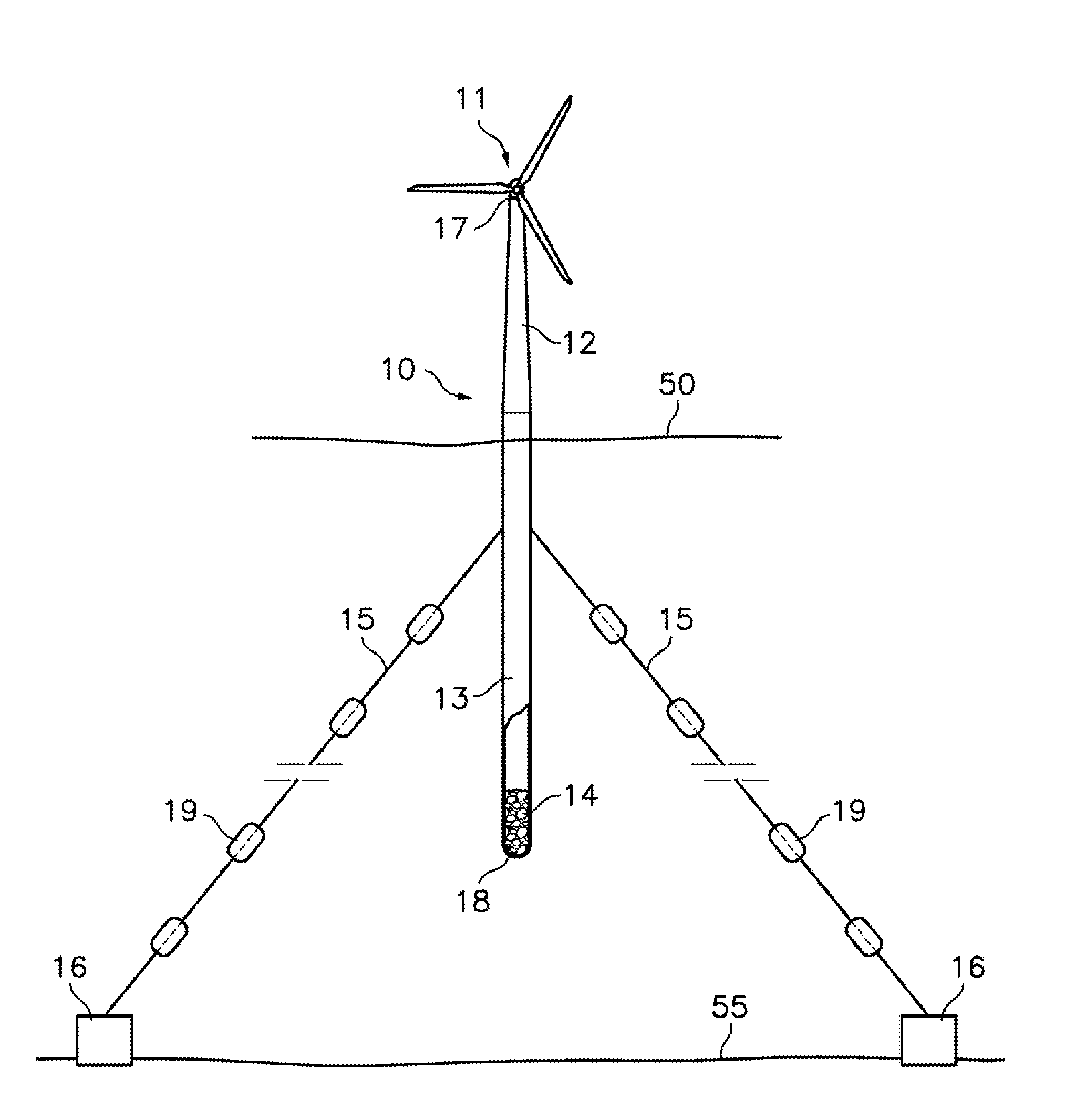
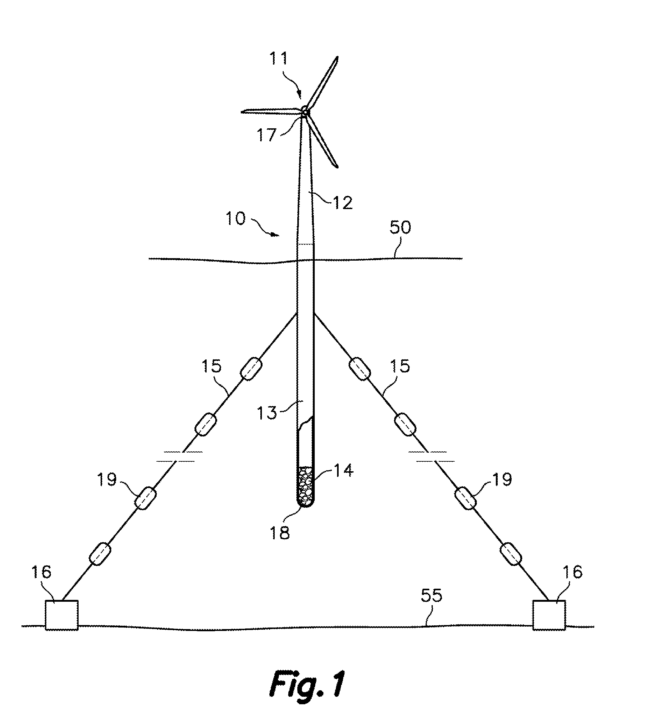
[0036]As seen FIG. 1, the floating structure for supporting a wind turbine of the present invention comprises, according to one embodiment, a hollow precast monolithic concrete body 10 made of reinforced and prestressed concrete including cylindrical and frustoconical sections having a total length comprised between 110 and 320 meters. The precast monolithic concrete body 10 comprises a hollow cylindrical lower section 13 finished at a lower end thereof by a hemispheric cap 18 and a hollow generally frustoconical upper section 12. The lower section 13, which is closed by the hemispheric cap 18, contains ballast and acts as a flotation element, and the upper section 12 is located, in an operative vertical position, above sea level and acts as a support for a wind turbine or another element.

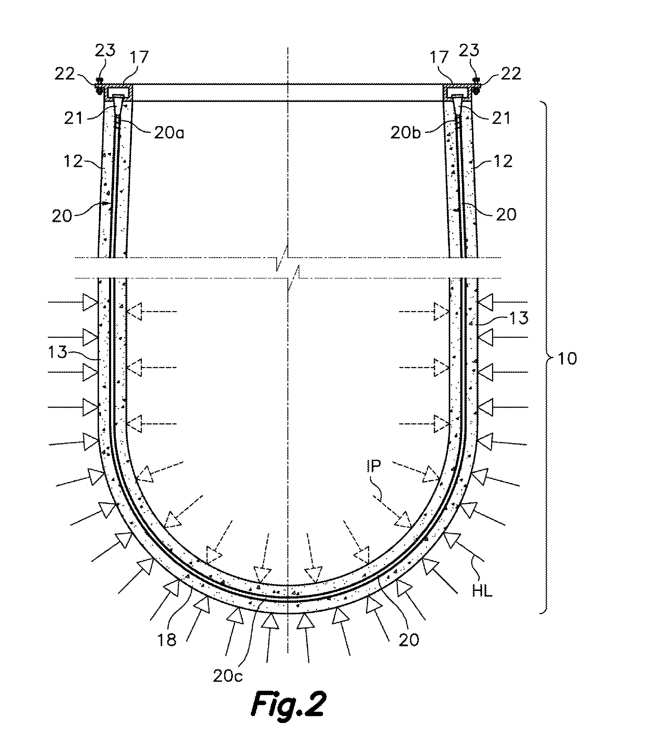
[0037]The precast monolithic concrete body 10 made of reinforced and prestressed concrete comprises active reinforcement members 20 (see FIG. 2) constituted by steel tendons inserted in protective ...


PUM


Abstract

The floating structure for supporting a wind turbine comprises a SPAR-type hollow precast monolithic body made of concrete prestressed by active reinforcement members having a cylindrical lower section (13) closed at its lower end by a hemispheric cap (18) which contains ballast (14) and acts as a flotation element and an upper section (12) located above sea level, which acts as a support for the wind turbine or other element. One or more of the active reinforcement members have opposite ends anchored to a steel ring-shaped plate (17) attached to an upper end of the upper section (12) and an intermediate section which has continuity within the hemispheric cap (18). The structure is preferably moored to the seabed by means of cable lines (15), through heavy weight elements (16) or suction piles capable of counteracting vertical and horizontal force components induced by the mooring lines.

Description

FIELD OF THE INVENTION[0001]The present invention relates to a floating structure comprising a precast monolithic concrete body for supporting high power wind turbines. The floating structure of the present invention is encompassed in the scope of renewable energies, specifically in harnessing wind energy in maritime areas having a great depth of more than 150 meters.[0002]In the context of this specification, the term “precast monolithic concrete body” is used to designate a body made of a single cast piece of concrete with no joints obtained by continuous pouring.[0003]In the context of this specification, the terms “upper” and “lower” refer to positions of parts of the precast monolithic concrete body when the floating structure is in its vertical operative position.PRIOR ART[0004]In the context of global trend that tends towards the use of renewable energies including, among others, the technology referring to extraction of electrical energy from the wind, it has experienced sig...

Claims


Application Information

Patent Timeline
IPC IPC(8): E02D27/42F03D11/04E02D27/52E02B17/02E02D27/50
CPCE02D27/425E02B17/02F03D11/045E02D27/52E02D27/50B63B5/20B63B21/27B63B21/29B63B2035/442B63B2035/446F05B2240/917F05B2240/93F05B2240/95F03D13/22F03D13/25Y02E10/72Y02E10/727Y02E10/728
Inventor MOLINS BORRELL, CLIMENTREBOLLO PERICOT, JOSEPCAMPOS HORTIGUELA, ALEXI
Owner UNIV POLITECNICA DE CATALUNYA
Learn More