Method for spectrophotometrically determining a blood oxygen parameter

a spectrophotometric and blood oxygen technology, applied in the field of non-invasive spectrophotometric medical devices, can solve the problems of discomfort and/or irritation experienced by subjects, and achieve the effect of avoiding the use of non-invasive medical devices

Active Publication Date: 2015-10-29
EDWARDS LIFESCIENCES CORP
View PDF2 Cites 11 Cited by
  • Summary
  • Abstract
  • Description
  • Claims
  • Application Information

AI Technical Summary

Benefits of technology

[0009]Embodiments of any of the above described aspects of the present invention may also include one or more of the following elements. For example, the NIRS sensor assembly may include a pad having at least one light detector aperture aligned with the light detector, and at least one light source aperture aligned with the at least one light detector. In this embodiment the subject contact layer may be disposed to cover both the light source and the at least one detector, and the at least one optically transmissive portion of the subject contact layer may include portions aligned with the light source and the at least one detector. As another example, the subject contact layer may be disposed within the light detector aperture. As another example, the subject contact layer may include an optically non-transmissive portion that is not aligned with the active area of the light detector. As another example, the subject contact layer may be made from one or more materials, including: a silicone foam, a polyethylene foam, a polyurethane foam, a polyvinyl chloride foam, a tricot fabric, a knit fabric, a loose weave fabric, a spunlace fabric, a microporous fabric, an elastic fabric, a hydrogel adhesive, a hydrocolloid adhesive, or an encapsulated gel. As another example, the sensor assembly may include a layer of electromagnetic (EMI) shielding disposed between the light detector and the subject contact layer. As another example, the sensor assembly may include a layer of EMI shielding incorporated into the subject contact layer. As another example, the sensor assembly may include a layer of electrically insulating material disposed between the light detector and the subject contact layer. As another example, the sensor assembly may include a layer of electrically insulating material is incorporated into the subject contact layer. As another example, the subject contact layer may have one or both of uniform optical attenuation characteristics and uniform light scattering characteristics.

Problems solved by technology

A problem common to non-invasive medical devices is discomfort and / or irritation experienced by a subject when a non-invasive medical device is in contact with the subject over a period of time.

Method used


Image

  • Method for spectrophotometrically determining a blood oxygen parameter
  • Method for spectrophotometrically determining a blood oxygen parameter
  • Method for spectrophotometrically determining a blood oxygen parameter

Examples


Embodiment Construction

[0020]The present disclosure describes embodiments of a NIRS sensor assembly; however, aspects of the present invention may be applied to other types of non-invasive medical devices, including, for example, pulse oximetry sensor assemblies.

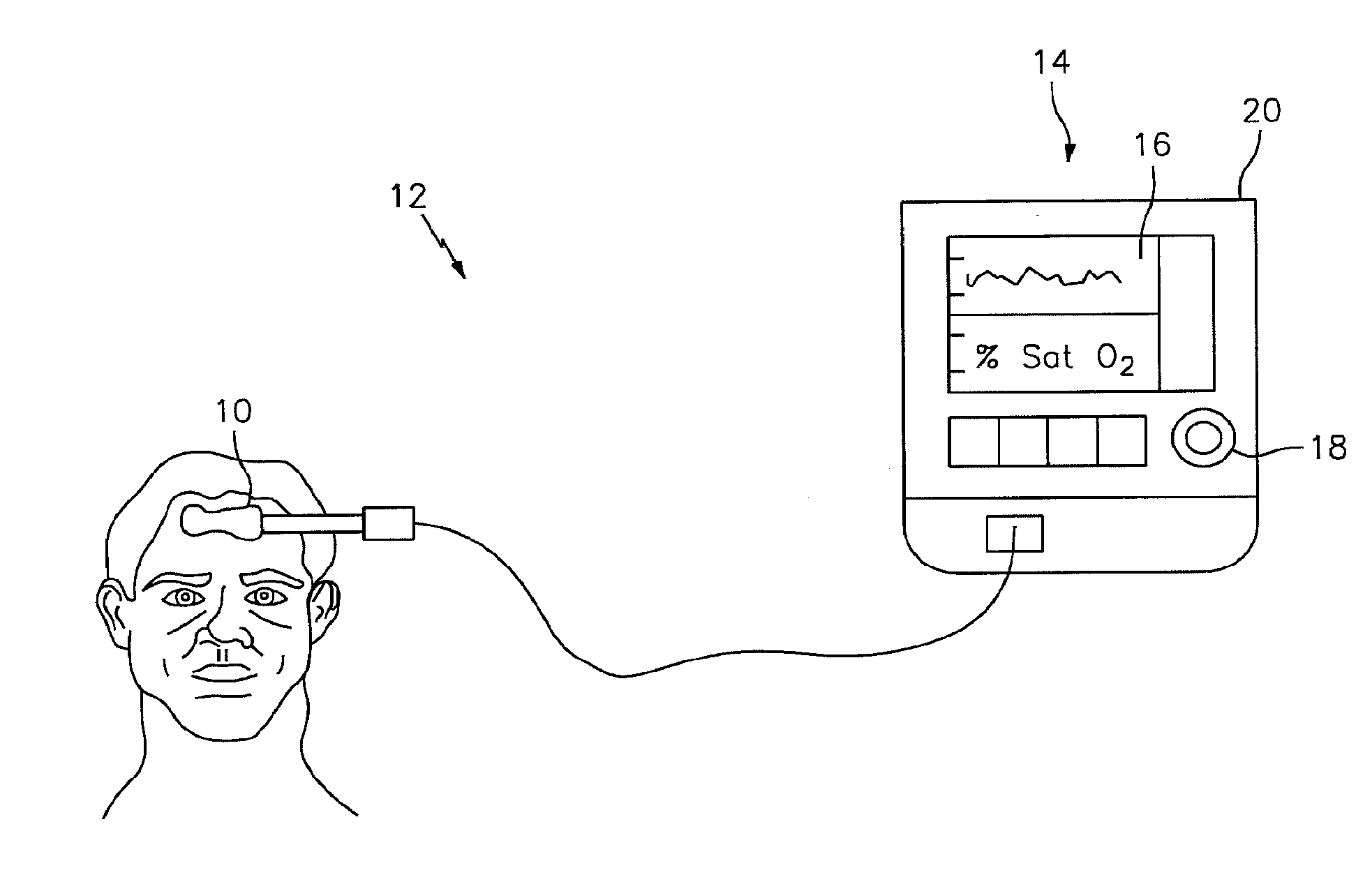
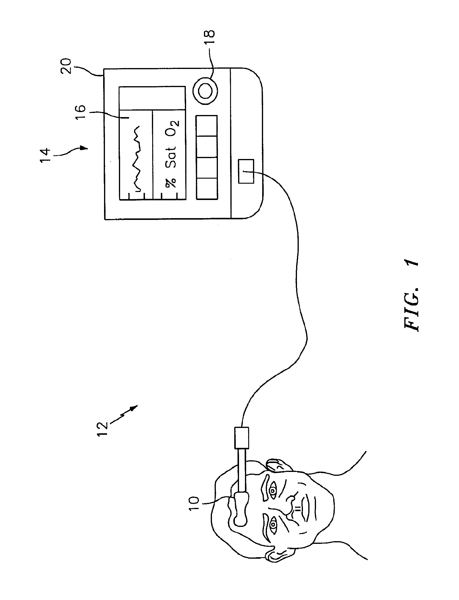
[0021]The NIRS sensor assembly described herein can be used in connection with various types of NIRS systems. In the embodiment illustrated in FIG. 1, the NIRS sensor assembly 10 is used in connection with a NIRS system 12 that includes a base unit 14. The base unit 14 includes a display 16, operator controls 18, and a processor 20 for providing signals to and / or receiving signals from the NIRS sensor assembly 10. The processor 20 includes one or more central processing units (CPUs) adapted (e.g., programmed) to selectively perform the functions necessary to perform the functions described herein. For example, the processor 20 is adapted to operate the NIRS sensor assembly 10 to emit light signals from the light source 22, to receive sensor signal...


PUM

PropertyMeasurementUnit
wavelength rangeaaaaaaaaaa

Abstract

According to an aspect of the present invention, a near infrared spectroscopy (NIRS) sensor assembly, system, and method for measuring a characteristic of a biological tissue is provided. The NIRS sensor assembly includes a light source, at least one light detector, and a subject contact layer. The light source is operable to emit light at one or more predetermined wavelengths. The light detector has an active area for detecting light emitted by the light source and passed through the biological tissue. The detector is operable to produce signals representative of the detected light. The subject contact layer is disposed to cover one or both of the light detector and the light source. The subject contact layer has at least one optically transmissive portion.

Description

[0001]This application claims priority to U.S. Patent Appln. No. 61 / 735,354 filed Dec. 10, 2012 and U.S. Patent Appln. No. 61 / 791,146 filed Mar. 15, 2013.BACKGROUND[0002]1. Technical Field[0003]Aspects of the present invention generally relate to non-invasive spectrophotometric medical devices, and more particularly relate to non-invasive medical devices that include a sensor with a subject contact layer.[0004]2. Background Information[0005]Non-invasive medical devices (e.g., near-infrared spectroscopy (NIRS) sensor assemblies, pulse oximetry sensor assemblies, etc.) often include one or more light emitting components (e.g., light emitting diodes (LEDs), laser diodes, etc.) that emit light signals (e.g., visible light signals, near-infrared light signals, etc.) and one or more light detecting components (e.g., photodiodes, charge-coupled devices, etc.) that detect light signals emitted by the light emitting components, for example, after such light signals pass through a biological ...

Claims


Application Information

Patent Timeline
Patent Type & Authority Applications(United States)
IPC IPC(8): G01N21/35A61B5/1455A61B5/00G01N33/49
CPCG01N21/35G01N33/4925A61B5/14552A61B2562/164A61B2562/0238A61B2562/146A61B5/6832A61B5/14553
Inventor DUFFY, KARENDALENE, MATTHEWGAMELIN, JOHNBENNI, PAUL
Owner EDWARDS LIFESCIENCES CORP
Why Eureka
Try Eureka