
Liquid crystal panel, method of manufacturing liquid crystal panel, transflective display device, and a method of controlling displaying of transflective display device

a technology of liquid crystal panels and display devices, which is applied in the manufacture of electrode systems, electric discharge tubes/lamps, instruments, etc., can solve the problems of reducing the display effect of the reflection region and the complex so as to simplify the process of fabricating the reflection layer and prevent electrostatic charges

Active Publication Date: 2015-10-29
BOE TECH GRP CO LTD
View PDF18 Cites 2 Cited by
  • Summary
  • Abstract
  • Description
  • Claims
  • Application Information

AI Technical Summary

Benefits of technology

The present invention provides a way to make a transflective liquid crystal panel that is easier to manufacture and prevents static charges from accumulating. This is done by a method of controlling the display and a simplified process for making the reflection layer. Overall, this invention makes it simpler to create a transflective display device.

Problems solved by technology

Therefore, the process for fabricating the reflection layer is complicated.
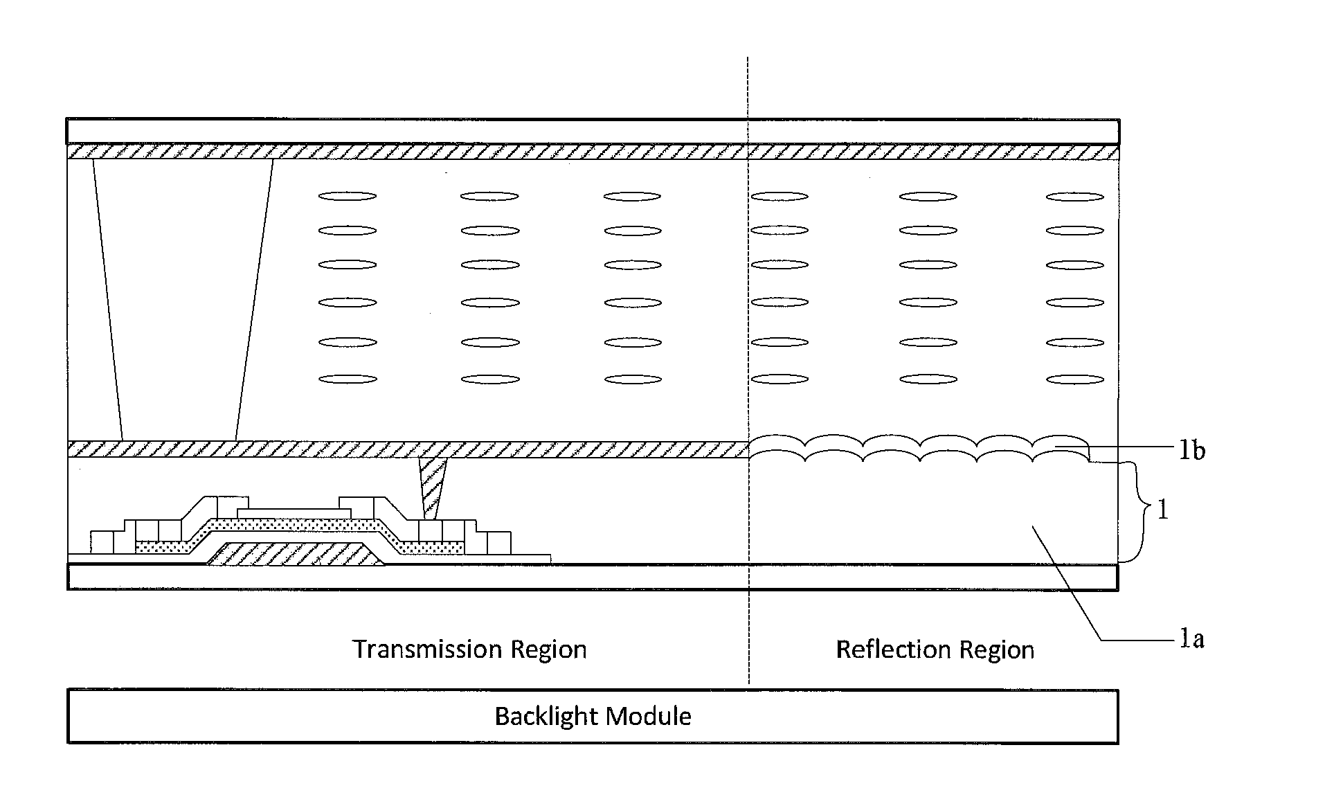
In addition, since the surface of the resin base and the metal film of the reflection layer have the uneven concavo-convex shape, and the orientation of the liquid crystal molecules in the reflection region is adversely affected, thereby reducing the displaying effect of the reflection region.

Method used


Image

  • Liquid crystal panel, method of manufacturing liquid crystal panel, transflective display device, and a method of controlling displaying of transflective display device
  • Liquid crystal panel, method of manufacturing liquid crystal panel, transflective display device, and a method of controlling displaying of transflective display device
  • Liquid crystal panel, method of manufacturing liquid crystal panel, transflective display device, and a method of controlling displaying of transflective display device

Examples


embodiment 1

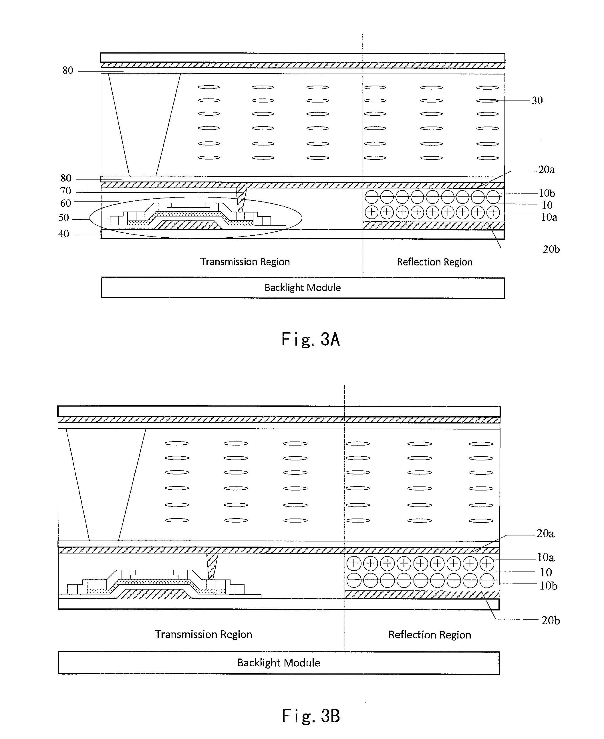
[0133]In the first embodiment, the method of manufacturing a transflective liquid crystal panel according to an embodiment of the present invention is explained by taking a method of manufacturing the transflective liquid crystal panel shown in FIG. 3A as an example.

[0134]In step A1, pixel units, arranged in a matrix, are formed on a first substrate 40, and a transmission region and a reflection region are disposed in each pixel unit.

[0135]As shown in FIG. 3A, the transmission region and the reflection region are disposed in one pixel unit on the first substrate 40.

[0136]In step A2, TFTs 50 each including a gate electrode, a source electrode, and a drain electrode are formed in the transmission regions, and elongated column electrode strips 20b corresponding to the reflection regions of column pixel units are formed in the reflection regions.

[0137]As shown in FIG. 3A, the TFTs 50 are located in the transmission regions while the elongated column electrode strips 20b are located in t...


PUM

PropertyMeasurementUnit
timeaaaaaaaaaa
particle sizeaaaaaaaaaa
reflectionaaaaaaaaaa

Abstract

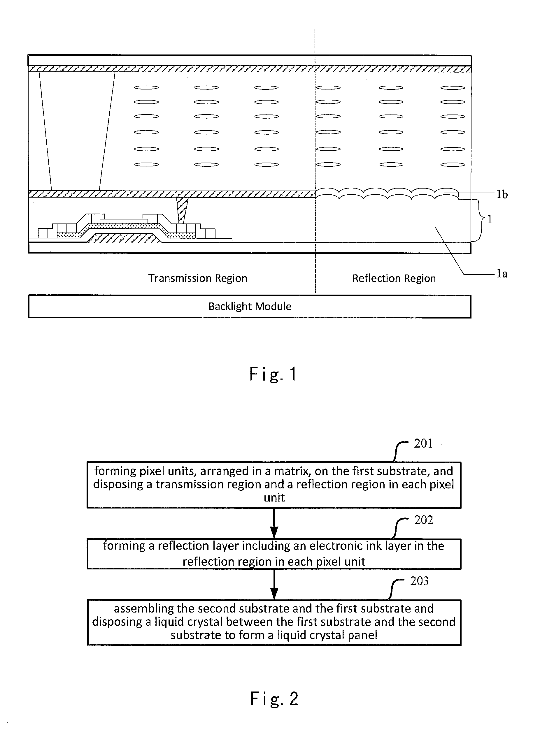
The embodiment of the present invention discloses a transflective liquid crystal panel, a method of manufacturing the transflective liquid crystal panel, a transflective display device, and a method of controlling displaying of the transflective display device to solve the technical problems that the process for fabricating the reflection layer is complicated, the metal film of the reflection layer will cause electrostatic charges to be accumulated, and the surface of the reflection layer has an uneven concavo-convex shape so that the orientation of the liquid crystal molecules in the reflection region is adversely affected. The transflective liquid crystal panel comprises pixel units arranged in a matrix, a transmission region and a reflection region disposed in each pixel unit, and a reflection layer disposed in the reflection region. The reflection layer includes an electronic ink layer.

Description

CROSS-REFERENCE TO RELATED APPLICATION[0001]This application claims the benefit of Chinese Patent Application No. 201410174880.4 filed on Apr. 28, 2014 in the State Intellectual Property Office of China, the whole disclosure of which is incorporated herein by reference.BACKGROUND OF THE INVENTION[0002]1. Field of the Invention[0003]Embodiments of the present invention relate to the field of liquid crystal display, and particularly to a transflective liquid crystal panel, a method of manufacturing the transflective liquid crystal panel, a transflective display device, and a method of controlling displaying of the transflective display device.[0004]2. Description of the Related Art[0005]A transflective liquid crystal panel comprises a color filter substrate, an array substrate, and a liquid crystal located between the color filter substrate and the array substrate. The array substrate is formed with a plurality of pixel units. Each pixel unit is provided with a transmission region and...

Claims


Application Information

Patent Timeline
Patent Type & Authority Applications(United States)
IPC IPC(8): G02F1/1335G02F1/133G02F1/1343G02F1/167G02F1/1677
CPCG02F1/133555G02F1/13318G02F1/13306G02F1/134336G02F1/167G02F2203/62G02F1/1677G02F2001/1678
Inventor WANG, XINXING
Owner BOE TECH GRP CO LTD
Learn More