Quality of Charge Detector for Use in Inductive Charging Systems

Active Publication Date: 2015-10-29
ACTIVE SEMI
View PDF11 Cites 23 Cited by
  • Summary
  • Abstract
  • Description
  • Claims
  • Application Information

AI Technical Summary

Benefits of technology

[0009]A QoC detector for use in inductive charging systems is disclosed. In exemplary embodiments, the QoC detector operates to detect a QoC metric associated with an inductive power transfer between an inductive charging device and a receiving device. The QoC metric indicates ener

Problems solved by technology

The rate of energy transfer can greatly affect the length of time necessary to charge a device's battery.
Unfortunately, an on/off charging indicator provides no informati

Method used


Image

  • Quality of Charge Detector for Use in Inductive Charging Systems
  • Quality of Charge Detector for Use in Inductive Charging Systems
  • Quality of Charge Detector for Use in Inductive Charging Systems

Examples


Embodiment Construction

[0027]The detailed description set forth below in connection with the appended drawings is intended as a description of exemplary embodiments of the invention and is not intended to represent the only embodiments in which the invention can be practiced. The term “exemplary” used throughout this description means “serving as an example, instance, or illustration,” and should not necessarily be construed as preferred or advantageous over other exemplary embodiments. The detailed description includes specific details for the purpose of providing a thorough understanding of the exemplary embodiments of the invention. It will be apparent to those skilled in the art that the exemplary embodiments of the invention may be practiced without these specific details. In some instances, well known structures and devices are shown in block diagram form in order to avoid obscuring the novelty of the exemplary embodiments presented herein.

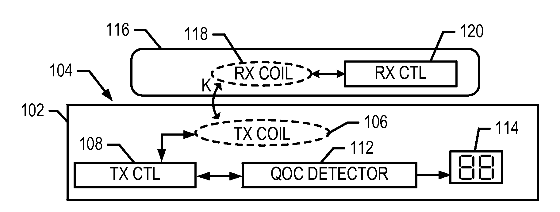
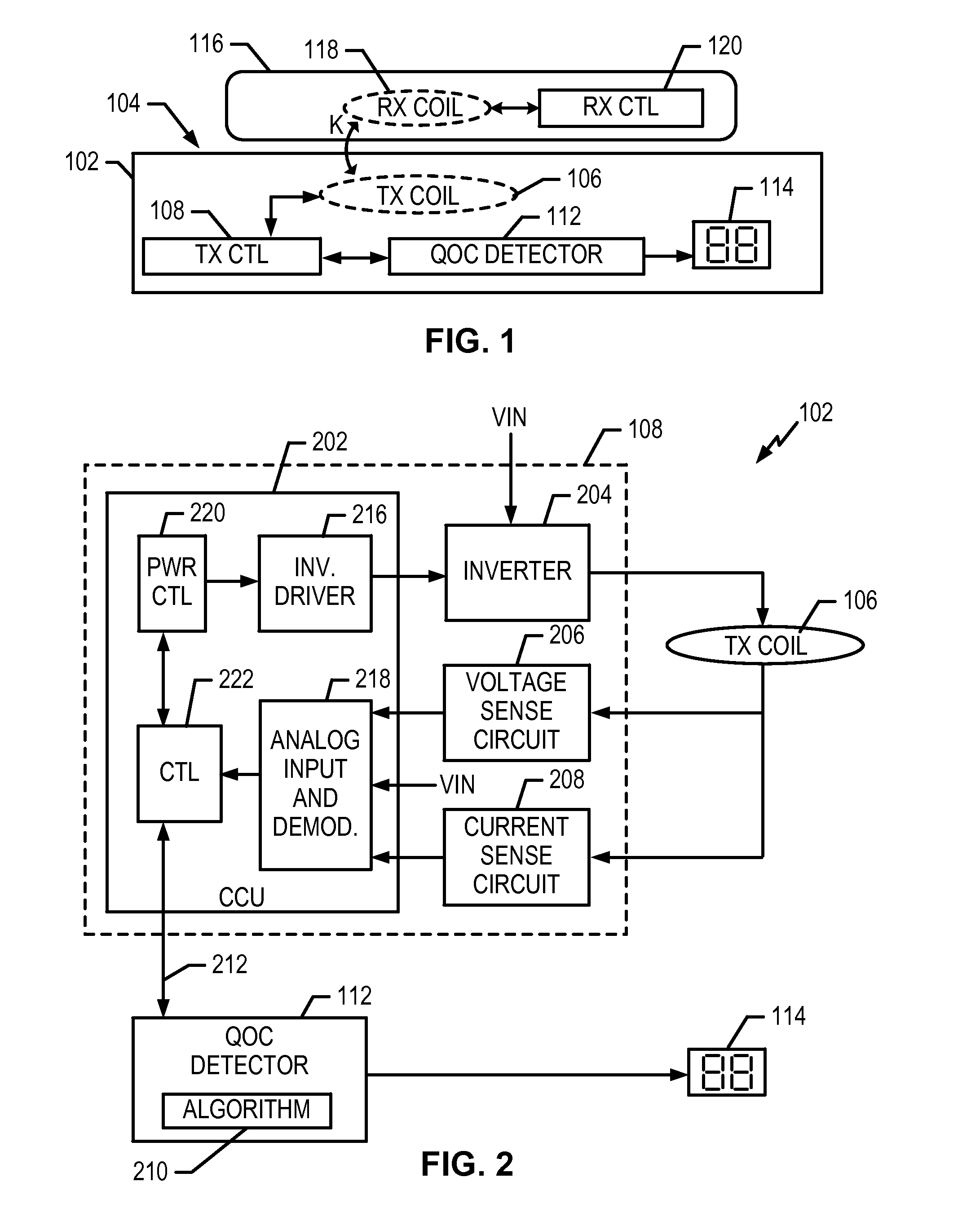
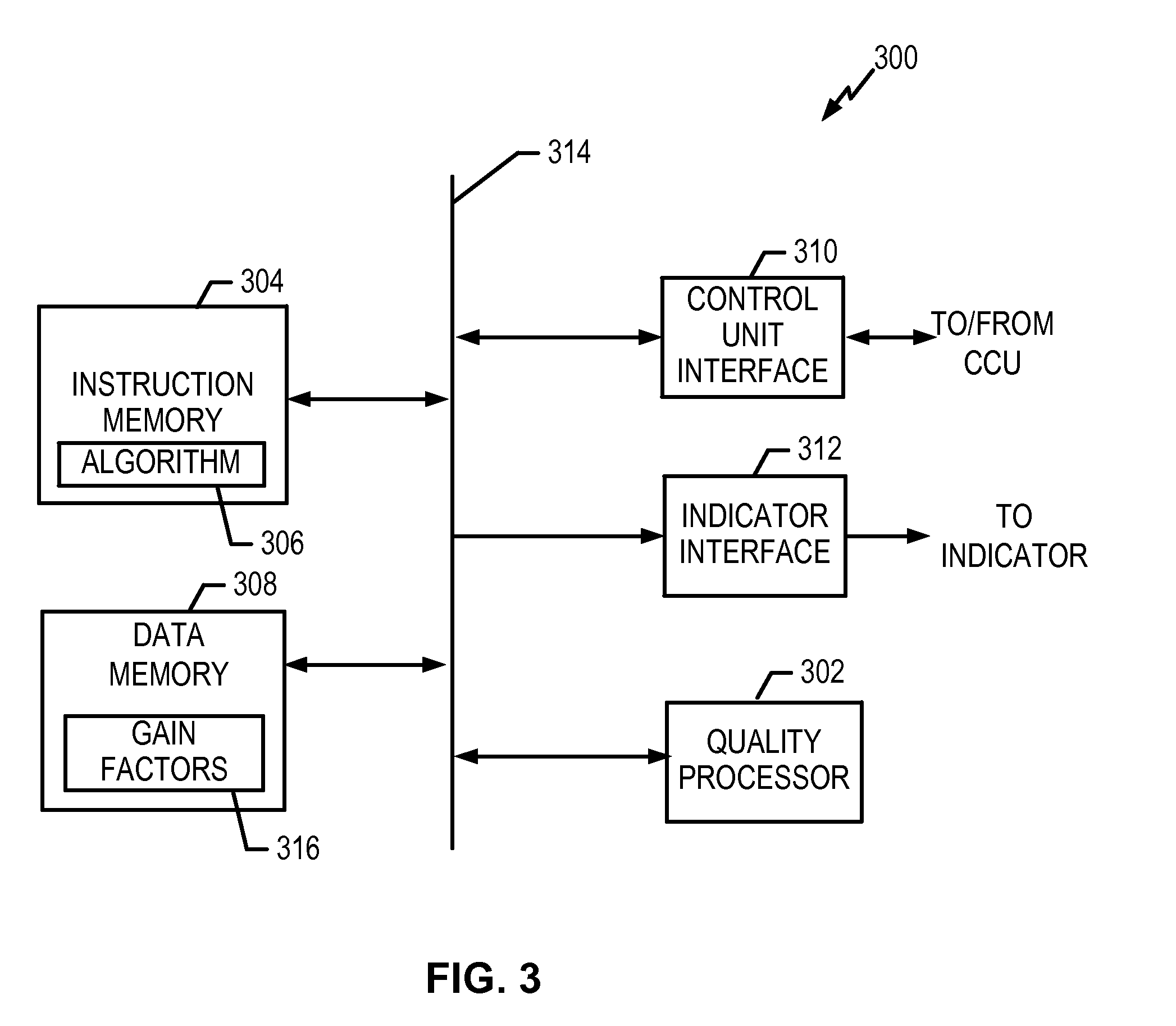
[0028]FIG. 1 shows an inductive charging device 102 that inc...


PUM


Abstract

A quality of charge (QoC) detector for use in inductive charging systems is disclosed. In an exemplary embodiment, an apparatus includes an inductor that receives a current signal to generate an electromagnetic field during a power transfer to an external device, and a quality detector to determine a quality metric associated with the power transfer. The apparatus also includes an indicator that indicates multiple states, where one of the multiple states is selected to indicate the quality metric.

Description

TECHNICAL FIELD[0001]The present application relates generally to the operation and design of inductive charging systems, and more particularly, to the operation and design of a quality of charge detector for use in inductive charging systems.BACKGROUND INFORMATION[0002]Inductive charging (also known as “wireless charging”) uses an electromagnetic field to transfer energy between two devices. For example, energy may be sent from a charging station through an inductive coupling to a portable device, which can then use that energy to charge batteries or operate the device. Inductive charging can be used to charge batteries in small devices like mobile phones or in larger devices like electric vehicles.[0003]An inductive charger typically utilizes a primary inductor or coil to create an alternating electromagnetic field from within a charging base station. A device with a secondary inductor or coil is positioned close to the charging base station so that the field generated by the prim...

Claims


Application Information

Patent Timeline
IPC IPC(8): G08B21/18G08B5/36H02J7/02
CPCG08B21/182G08B5/36H02J7/025H02J50/12H02J50/80H02J7/00034H02J50/90H02J50/10
Inventor SOUSA, MARCCIERI, MARK
Owner ACTIVE SEMI
Why Eureka
Try Eureka