Self power sshi circuit for piezoelectric energy harvester

a piezoelectric energy harvester and self-power technology, applied in piezoelectric/electrostrictive/magnetostrictive devices, basic electric elements, electric apparatus, etc., can solve the problems of small power generated from piezoelectric energy harvesters, inconvenient use, and large amount of power dissipation of piezoelectric materials, etc., to achieve increased output power, reduce losses, and increase efficiency

Active Publication Date: 2015-10-29
KING SAUD UNIVERSITY
View PDF3 Cites 40 Cited by
  • Summary
  • Abstract
  • Description
  • Claims
  • Application Information

AI Technical Summary

Benefits of technology

[0016]The present invention relates to a new self-power synchronized switch harvester on inductor device which uses two capacitors (passive elements) to detect the flipping point of terminal voltage and replaces many active elements as used on other circuits, such as resistors, diodes and operational amplifiers. The new circuit showed a significant reduction in losses, increased output powers, increased efficiency, low costs and increased reliability.

Problems solved by technology

For example, a considerable amount of power is dissipated in the piezoelectric materials to flip the output voltage through an internal capacitor and resistor of a piezoelectric device.
The power generated from a piezoelectric energy harvester is very small to be used to feed loads directly and it is not suitable to be used in most of the applications without battery storage or super-capacitor to accumulate the generated power to be used when required.
This technique is characterized by high output voltage and low current which is not suitable for small battery storage with low voltage.
Operating a PEH circuit in low voltage will considerably reduce the efficiency and the extracted power.
This considerably reduces the extracted energy and efficiency of the piezoelectric energy harvesting circuit.
BD-SSHI technique suffers from low efficiency and it is not self-started when the battery loses its charge.
This circuit [24] dissipated a considerable amount of power in feeding and biasing the comparator and other elements of the circuit.

Method used


Image

  • Self power sshi circuit for piezoelectric energy harvester
  • Self power sshi circuit for piezoelectric energy harvester
  • Self power sshi circuit for piezoelectric energy harvester

Examples


Embodiment Construction

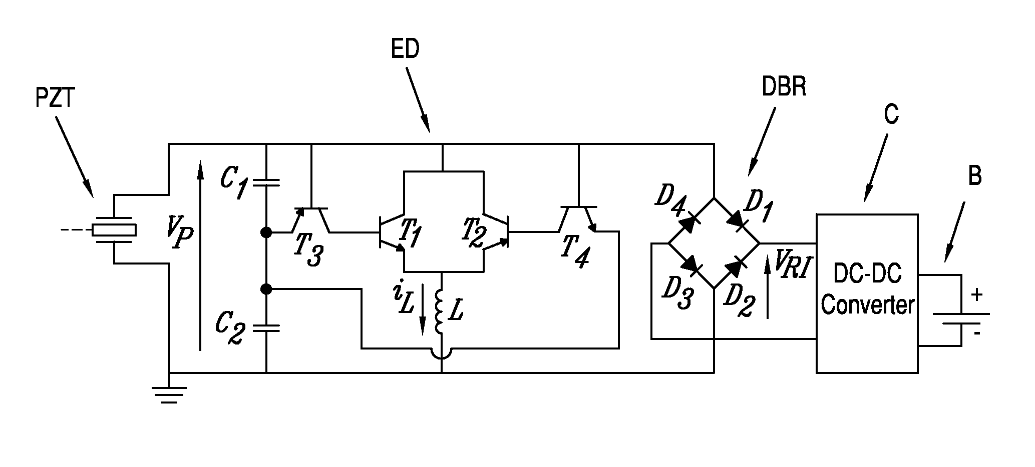
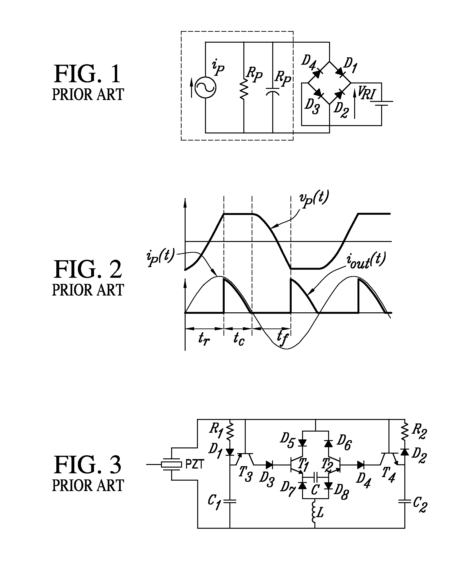
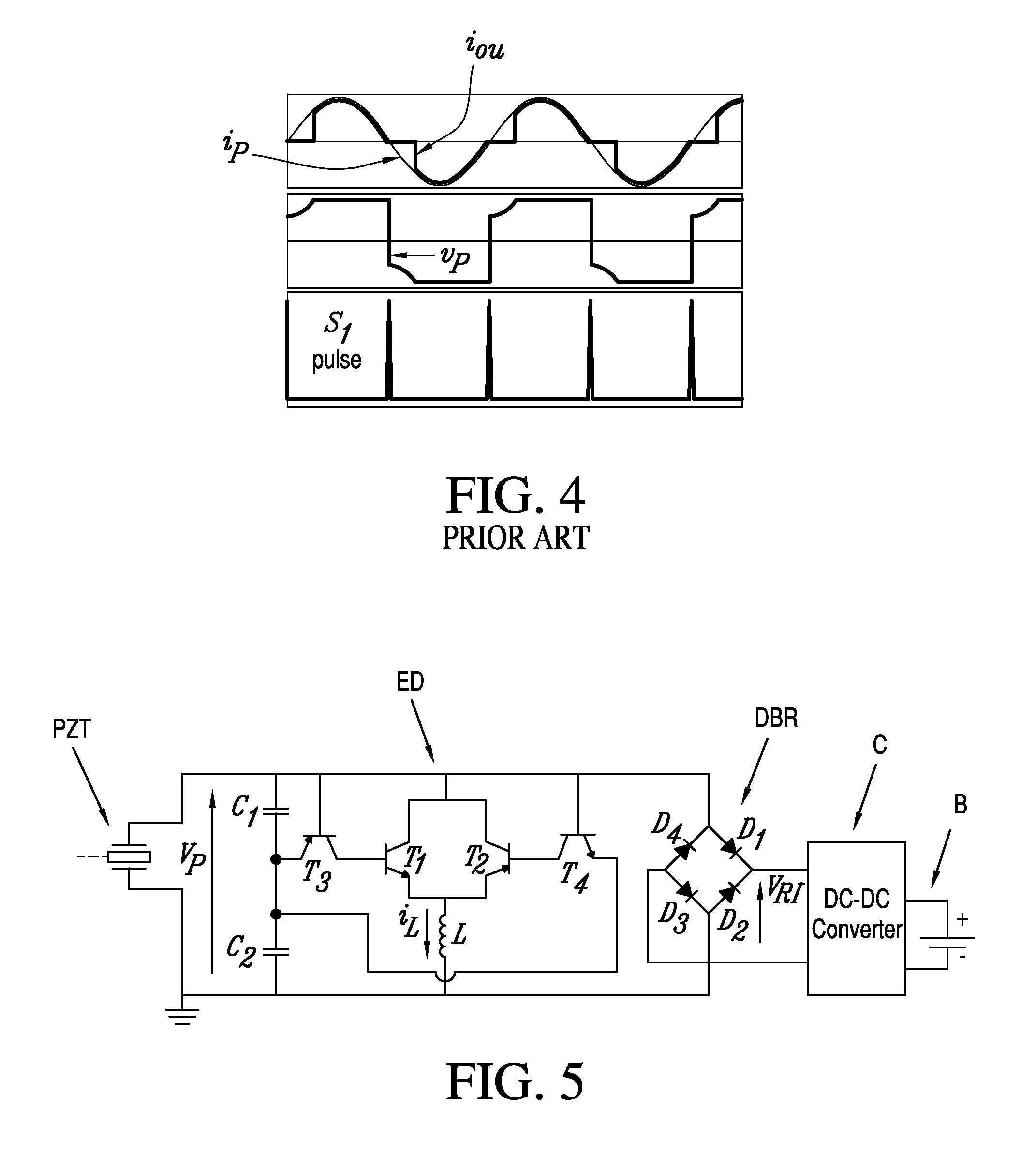
[0024]The self-power synchronized switch harvesting on inductor circuit of the invention for harvesting energy from a piezoelectric element comprises an envelope detector having passive elements connected in parallel with the piezoelectric element and functioning as negative and positive voltage detectors. An inductor is connected in parallel with the capacitors, and switch means are connected in circuit with the capacitors and inductor to control flipping of positive and negative voltage from the piezoelectric element to the inductor. A full-wave rectifier is connected in the circuit to convert the AC output of the piezoelectric element to DC voltage, and a DC-DC converter is connected to receive the rectified voltage and supply it to a load. An equivalent circuit for a piezoelectric element, including the piezoelectric element PZT of the present invention, includes an internal capacitor Cp as depicted in the area bounded by broken lines in FIG. 1.

[0025]In a preferred embodiment, a...


PUM


Abstract

A self-power synchronized switch harvesting on inductor circuit for harvesting energy from a piezoelectric element generating an AC voltage, comprises an envelope detector having first and second capacitors connected in parallel with the piezoelectric element and functioning as negative and positive voltage detectors. An inductor is connected in parallel with the capacitors, and transistors are connected in circuit with the capacitors and inductor and are responsive to a change in voltage across the first capacitor from positive to negative to enable flow of positive voltage to the inductor until terminal voltage reaches a certain amount and current in the inductor reaches zero. A full-wave rectifier is connected to convert the AC output of the piezoelectric element to DC voltage, and a DC-DC converter is connected to adapt the power output of the rectified voltage.

Description

FIELD OF THE INVENTION[0001]This invention relates to a self-power synchronized switch harvesting on inductor (SSHI) circuit and more particularly to a new self-powered SP-SSHI that uses only passive elements, i.e. two capacitors, to detect the flipping points of terminal voltage instead of using several resistors and diodes or integrated circuits as in an operational amplifier. Compared to existing circuits, the new circuit shows a significant reduction in losses, increased output powers, increased efficiency, lower cost and increased reliability.BACKGROUND OF THE INVENTION[0002]A need for a wireless electrical power supply has spurred an interest in piezoelectric energy harvesting on the extraction of electrical energy using a vibrating piezoelectric device according to G. K. Ottman et al. in an article entitled “Adaptive Piezoelectric Energy Harvesting Circuit for Wireless Remote Power Supply,” IEEE Transaction on Power Electronics, Vol. 17, No. 5, September 2002. As stated there...

Claims


Application Information

Patent Timeline
Patent Type & Authority Applications(United States)
IPC IPC(8): H02N2/18
CPCH02N2/181
Inventor ELTAMALY, ALI M.ADDOWEESH, KHALED
Owner KING SAUD UNIVERSITY
Why Eureka
Try Eureka