Image capturing apparatus and method for controlling image capturing apparatus

a technology of image capturing apparatus and image sensor, which is applied in the direction of color television details, television systems, radio frequency controlled devices, etc., can solve the problems of difficult high-speed operation, difficult to excessively increase the proportion of phase difference detection pixels arranged, and take a long time to complete the process, so as to increase the circuit scale, cost and read time of an image sensor, and reduce the effect of image quality

Active Publication Date: 2015-10-29
CANON KK
View PDF7 Cites 6 Cited by
  • Summary
  • Abstract
  • Description
  • Claims
  • Application Information

AI Technical Summary

Benefits of technology

[0015]The present invention has been made in consideration of the above situation, and required pixel signals are read out with accuracy sufficient for phase difference detection without an increase in the circuit scale, cost, and read time of an image sensor, and without a decrease in image quality.

Problems solved by technology

Therefore, it takes a long time to complete the process.
Therefore, it is difficult to perform a high-speed operation.
Therefore, it is difficult to excessively increase the proportion of phase difference detection pixels arranged.
Therefore, although the same reading circuit configuration as that which is used when no phase difference detection pixel is included can be used, the resolution for phase difference detection is low.
In particular, a double number of storage capacitors, which occupy a relatively large area in an image sensor, are required, and control lines are complicated, and therefore, the area of a circuit around the image sensor is likely to increase.
Moreover, an arrangement for subtracting the A-signal from the (A+B)-signal to obtain the B-signal is required in the entire system, disadvantageously leading to large circuit size and high cost.
Thus, the time it takes to write the column circuit increases, and the horizontal transfer time is simply two times as long, and therefore, it is difficult to perform high-speed reading.
However, when the cycle of horizontal synchronization is changed only for the particular rows, there is a significantly large load on the system.

Method used


Image

  • Image capturing apparatus and method for controlling image capturing  apparatus
  • Image capturing apparatus and method for controlling image capturing  apparatus
  • Image capturing apparatus and method for controlling image capturing  apparatus

Examples


first embodiment

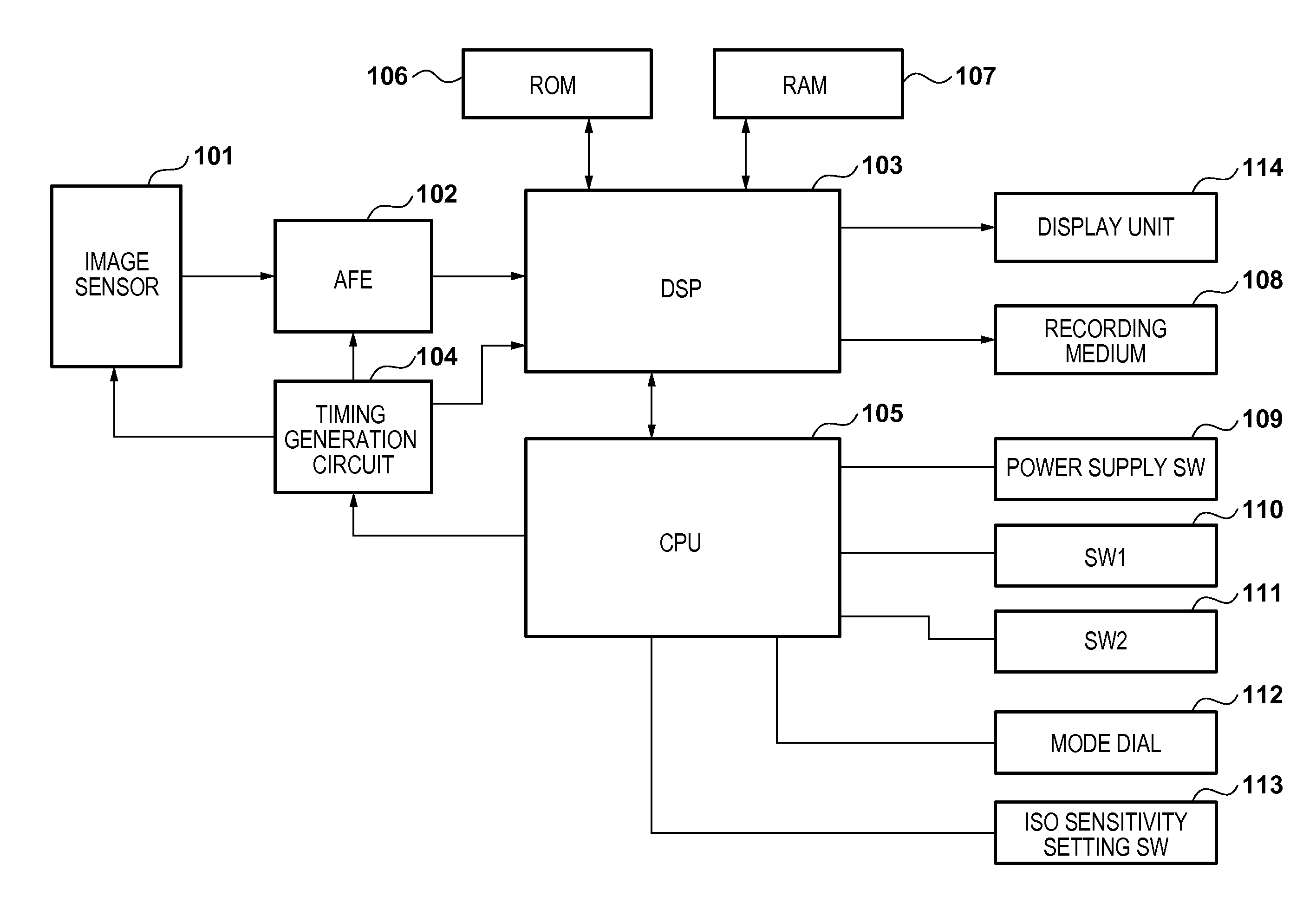
[0039]FIG. 1 is a block diagram of an image capturing apparatus according to a first embodiment of the present invention. An image sensor 101 includes an amplifier circuit (not shown) which switches between gains, depending on ISO sensitivity. An analog front end (AFE) 102 includes an A / D converter which converts an analog signal from the image sensor 101 into a digital signal, and also has a function of clamping a dark offset level.

[0040]A digital signal processor (DSP) 103 performs various correction processes, a development process, and a compression process on an image signal output from the AFE 102. The DSP 103 may also perform various correction processes on image signal in a RAM 107. The DSP 103 also performs a correction process on various types of noise occurring in the image sensor 101, defective pixel detection, and a correction process on outputs of a defective pixel and phase difference detection pixels, a correction process on pixels around the phase difference detecti...

second embodiment

[0122]Next, a second embodiment according to the present invention will be described. In the first embodiment, it has been described that two rows are successively read out using the second scanning method, and phase difference detection is performed using an A-pixel signal output from G-filter pixels in the row which is read out earlier, and a B-pixel signal output from G-filter pixels in the row which is read out later. In contrast to this, in the second embodiment, initially, a combined signal for image data is read out every five rows, i.e., while four rows are skipped between each read row, and next, the four skipped rows are successively read out. In the latter readout, the image sensor is driven so that a signal is read out from the A-pixels in the two rows which are read out earlier, and a signal is read out from the B-pixels in the two rows which are read out later, and phase difference detection is performed using all pixel information of the Bayer filter array. FIGS. 13A ...


PUM


Abstract

An image capturing apparatus comprises: an image sensor including a pixel region including a plurality of pixel units, arranged in a matrix, each having first and second photoelectric conversion units, and a storage unit provided for each column; and a driving unit configured to drive the image sensor by, for each pixel unit to be read of the plurality of pixel units, exclusively selecting an operation of combining a signal of the first photoelectric conversion unit and a signal of the second photoelectric conversion unit for each pixel unit and outputting the combined signal to the storage unit, an operation of reading a signal from the first photoelectric conversion unit of each pixel unit to the storage unit, or an operation of reading a signal from the second photoelectric conversion unit of each pixel unit to the storage unit.

Description

BACKGROUND OF THE INVENTION[0001]1. Field of the Invention[0002]The present invention relates to image capturing apparatuses and methods for controlling image capturing apparatuses.[0003]2. Description of the Related Art[0004]In the related art, the contrast detection scheme is known in automatic focus detection and automatic focus control of an image capturing apparatus as a typical technique of using a flux of light passing through an imaging lens. In this scheme, an image sensor is used as a sensor for focus detection, an output signal of the image sensor is evaluated, and the position of the imaging lens is moved so that the contrast information is maximized, whereby the focus can be adjusted.[0005]However, the contrast information needs to be evaluated each time the imaging lens is moved to a different position. In addition, after the highest contrast has eventually been found as a result of the evaluation, the imaging lens is moved back to the position where the highest contra...

Claims


Application Information

Patent Timeline
Patent Type & Authority Applications(United States)
IPC IPC(8): H04N5/243H04N5/378H04N5/374
CPCH04N5/243H04N5/378H04N5/374H01L27/146H04N5/00H04N23/672H04N25/704H04N25/134H04N23/667H04N25/445H04N25/46H04N25/778H04N25/75H04N23/76H04N25/76
Inventor KITANI, KAZUNARI
Owner CANON KK
Why Eureka
Try Eureka