Oscillation circuit, electronic apparatus, and moving object

Active Publication Date: 2014-04-03
SEIKO EPSON CORP
View PDF3 Cites 3 Cited by
  • Summary
  • Abstract
  • Description
  • Claims
  • Application Information

AI Technical Summary

Benefits of technology

The invention provides an oscillation circuit, electronic apparatus, and moving object that can expand the width of capacitance while maintaining the linearity of change in capacitance with respect to control voltage. This means that these objects can change frequency with greater ease and without increasing the size or power consumption of the circuit. The circuit includes a function to adjust the reference voltages, which helps to achieve better linearity and flat sensitivity of the set of variable capacitive elements. By using the intermediate voltage between reference voltages of other sets of variable capacitive elements, the minimum sensitivity of the set of elements can be lowered without requiring a separate circuit. This reduces the circuit size and power consumption, and avoids large noise in the set of minimum sensitivity elements. Overall, this invention enables electronic apparatus and moving objects to achieve the necessary frequency variable width with user-friendliness.

Problems solved by technology

In a discrete oscillator, although a variable capacitive element having a large change in capacitance is selected to constitute a circuit, when implementing an oscillation circuit in the form of an integrated circuit, the characteristics of usable variable capacitive elements are limited.
However, when an integrated circuit is used, the variable amount of a usable variable capacitive element is limited, and thus there is a problem in that a necessary frequency variable width or linearity is not obtained.
Accordingly, when the method disclosed in JP-A-2007-19565 is applied to the TCXO, circuit scale and power consumption tend to increase.

Method used


Image

  • Oscillation circuit, electronic apparatus, and moving object
  • Oscillation circuit, electronic apparatus, and moving object
  • Oscillation circuit, electronic apparatus, and moving object

Examples


first embodiment

1. First Embodiment

1.1. Outline of Oscillation Circuit

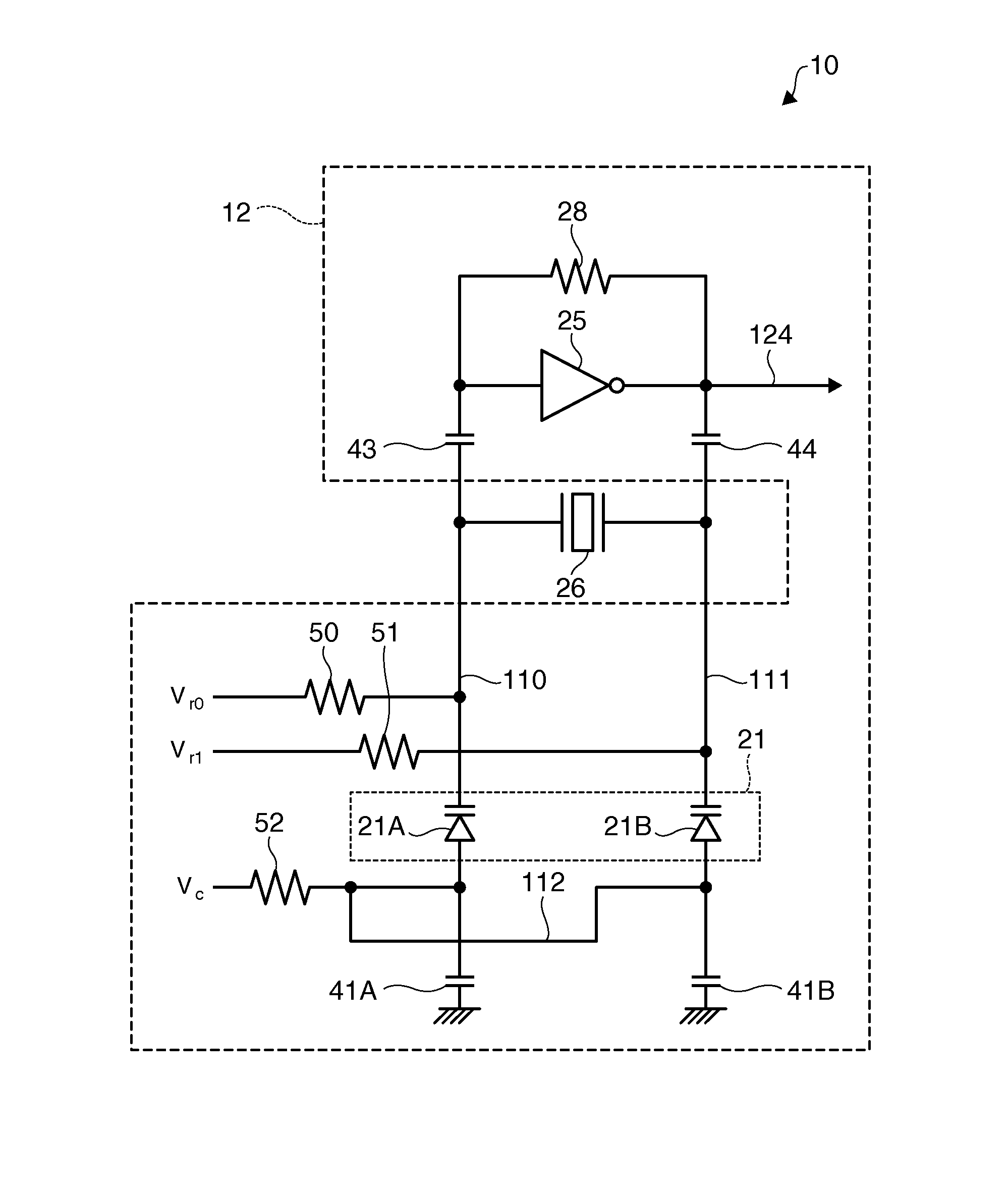
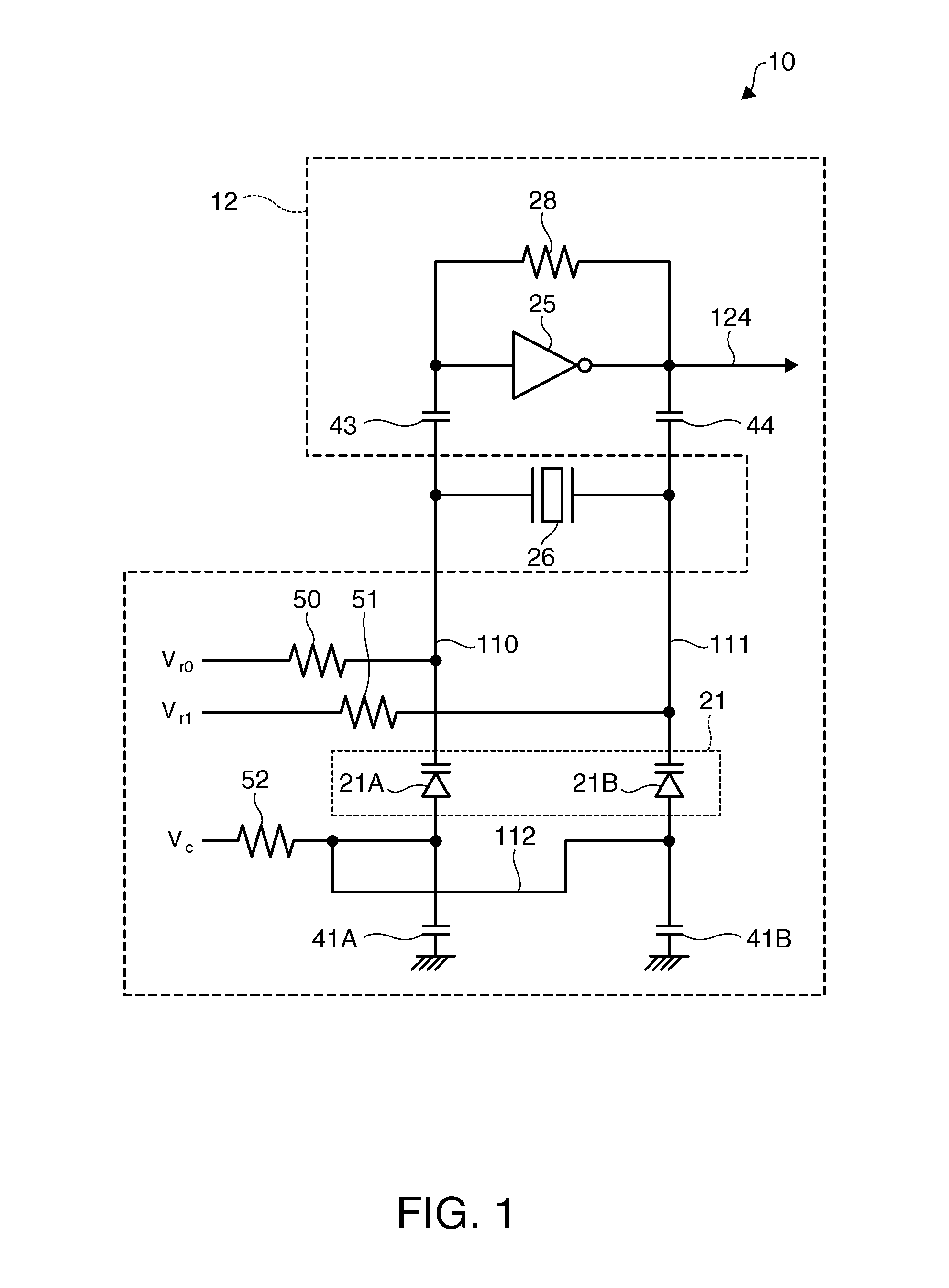
[0050]FIG. 1 is a diagram showing a configuration example of an oscillation circuit 12 of a first embodiment. The oscillation circuit 12 of this embodiment forms a part of a temperature compensated X'tal oscillator (TCXO). In the oscillation circuit 12 of this embodiment, some of elements described below may be omitted or changed, or other elements may be added.

[0051]The oscillation circuit 12 of this embodiment includes a feedback resistor 28 and an inverter 25, and is connected to a crystal resonoator 26. The inverter 25 has a property to amplify an input signal, and corresponds to an amplification element according to the invention. The crystal resonator 26 corresponds to an resonator element according to the invention. As shown in FIG. 1, the oscillation circuit 12 is connected to the crystal resonator 26, and an oscillation loop is formed from an output to an input of the inverter 25. The oscillation circuit 12 amplifies a s...

second embodiment

2. Second Embodiment

2.1. Outline of Oscillation Circuit

[0096]FIG. 11 is a diagram showing a configuration example of an oscillation circuit 12 of a second embodiment. Unlike the first embodiment, the oscillation circuit 12 of this embodiment includes a voltage generation unit 60 which generates reference voltages Vr0 and Vr1 and a control voltage VC. The same elements as those in FIGS. 1 to 10 are represented by the same reference numerals, and description thereof will not be repeated.

[0097]In the oscillation circuit 12 of this embodiment, the voltage generation unit 60 can easily adjust the reference voltages Vr0 and Vr1. For this reason, fine adjustment is possible such that variable sensitivity of the varactors 21A and 21B is flat (a state where change in frequency of an oscillation signal is unbiased with respect to a control voltage), that is, more excellent linearity is exhibited.

application example

3. Application Example

3.1. Electronic Apparatus

[0113]An electronic apparatus 300 which is an application example to the first embodiment, the second embodiment, and the modifications thereof will be described referring to FIGS. 16 and 17. The same elements as those in FIGS. 1 to 15 are represented by the same reference numerals, and descriptions thereof will not be repeated.

[0114]FIG. 16 is a functional block diagram of the electronic apparatus 300 of the application example. The electronic apparatus 300 of the application example includes an oscillation circuit 12 connected to a crystal resonator 26, a central processing unit (CPU) 320, an operating unit 330, a read only memory (ROM) 340, a random access memory (RAM) 350, a communication unit 360, a display unit 370, and a sound output unit 380. In the electronic apparatus 300 of this application example, some of the constituent elements (respective units) of FIG. 16 may be omitted or changed, or other constituent elements may be a...


PUM


Abstract

An oscillation circuit is connected to a resonator element (crystal resonator) and oscillates a resonator element to output an oscillation signal. The oscillation circuit includes an amplification element (inverter), and a set of variable capacitive elements having at least two variable capacitive elements, which are connected to an oscillation loop from an output to an input of the amplification element and the capacitance values thereof are controlled with potential differences between reference voltages and a variable control voltage. In each variable capacitive element of a set of variable capacitive elements, the common control voltage is applied to one terminal, and the reference voltage which differs between the variable capacitive elements is input to the other terminal.

Description

BACKGROUND[0001]1. Technical Field[0002]The present invention relates to an oscillation circuit, an electronic apparatus, a moving object, and the like.[0003]2. Related Art[0004]In order to make a frequency of an oscillation circuit variable, a method in which a voltage is applied to a variable capacitive element arranged in the oscillation circuit to change capacitance is known. An oscillator which controls a frequency with voltage is generally called a voltage controlled X'tal oscillator (VCXO). As an oscillator in which a frequency deviation is suppressed with respect to temperature using this principle, a temperature compensated X'tal oscillator (TCXO) is known.[0005]In a discrete oscillator, although a variable capacitive element having a large change in capacitance is selected to constitute a circuit, when implementing an oscillation circuit in the form of an integrated circuit, the characteristics of usable variable capacitive elements are limited. That is, if an oscillation ...

Claims


Application Information

Patent Timeline
IPC IPC(8): H03L7/16
CPCH03L7/16H03L1/023H03B5/364H03B5/36H03B1/00
Inventor ISHIKAWA, MASAYUKIYAMAMOTO, TAKEHIROITASAKA, YOSUKE
Owner SEIKO EPSON CORP
Why Eureka
Try Eureka