Ultrasound diagnostic apparatus

Active Publication Date: 2015-11-05
FUJIFILM CORP
View PDF1 Cites 5 Cited by
  • Summary
  • Abstract
  • Description
  • Claims
  • Application Information

AI Technical Summary

Benefits of technology

[0008]The present invention has been accomplished in order to solve the aforementioned problems in the prior art, and an object thereof is to provide an ultrasound diagnostic apparatus capable of suppressing deterioration of image quality o

Problems solved by technology

That is, a larger amount of noise of higher intensity is included in the reception signal output from the organic piezoelectric element compared to the reception signal output from the inorganic piezoelectric element, and thus a large amount of noise of high intensity is included in the ultrasound image produced based on the reception signals output from the organic piezoelectric elements.
For this reason, although the ultrasound

Method used


Image

  • Ultrasound diagnostic apparatus
  • Ultrasound diagnostic apparatus
  • Ultrasound diagnostic apparatus

Examples


Example

Embodiment 1

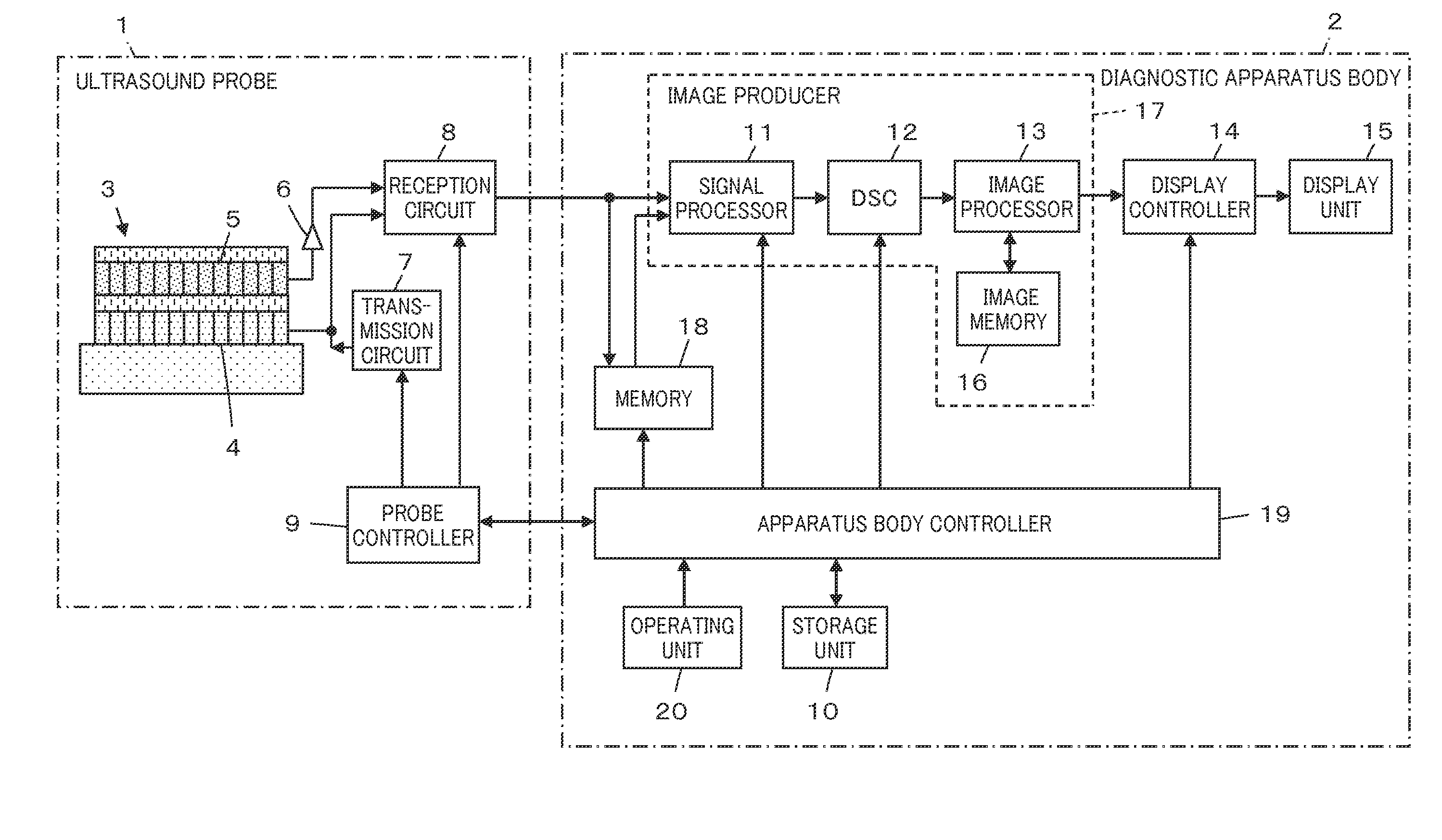
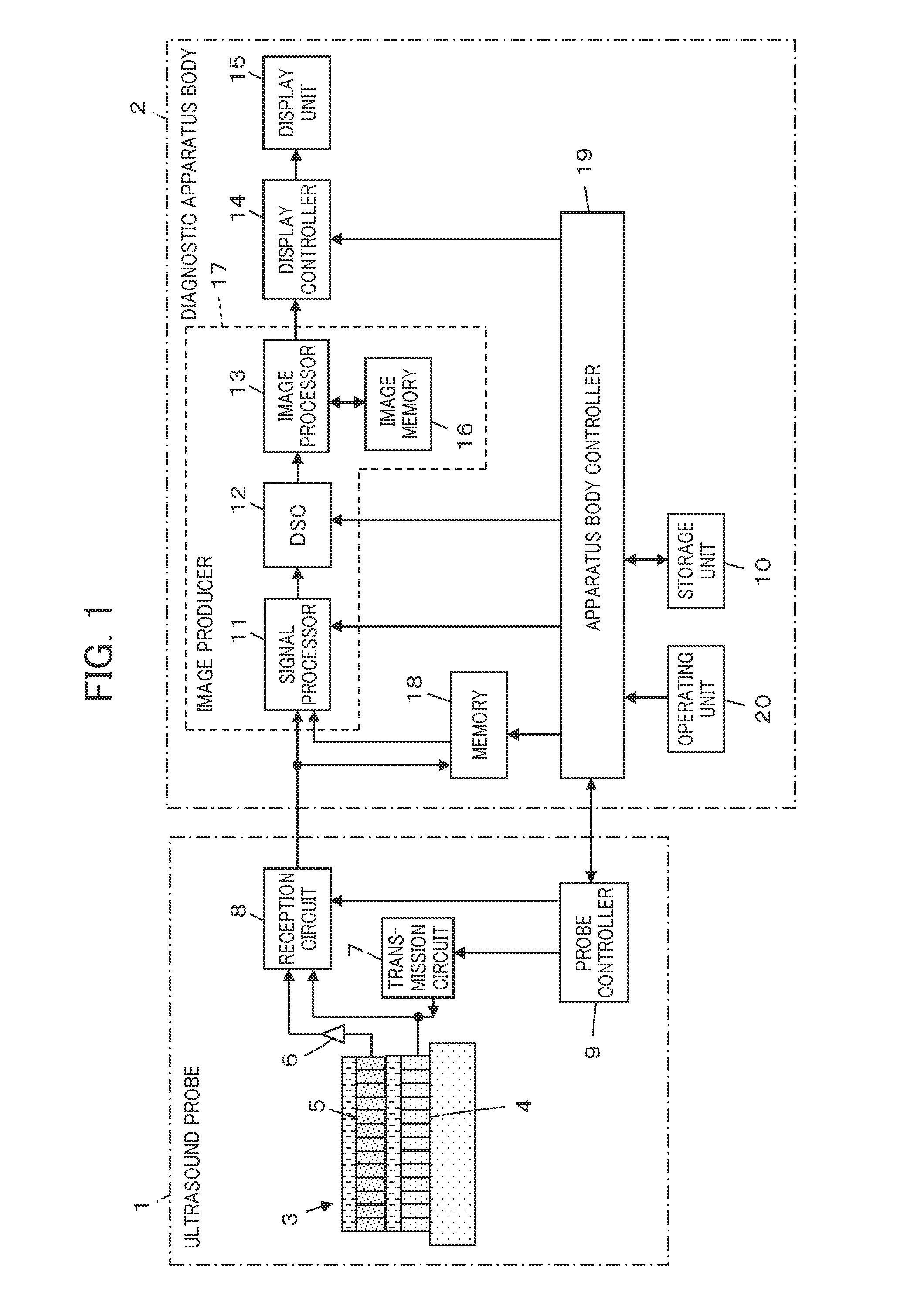
[0021]FIG. 1 shows the configuration of an ultrasound diagnostic apparatus according to Embodiment 1. The ultrasound diagnostic apparatus includes an ultrasound probe 1, and a diagnostic apparatus body 2 connected to the ultrasound probe 1.

[0022]The ultrasound probe 1 has a laminated transducer array 3. The laminated transducer array 3 has a plurality of inorganic piezoelectric elements 4 which are arranged in array form, and a plurality of organic piezoelectric elements 5 which are formed and laminated on the inorganic piezoelectric elements 4 and are arranged in array form. A corresponding preamplifier 6 is connected to each of the organic piezoelectric elements 5.

[0023]A transmission circuit 7 and a reception circuit 8 are each connected to the inorganic piezoelectric elements 4, and the reception circuit 8 is connected to the preamplifiers 6 as connected to the organic piezoelectric elements 5. Furthermore, a probe controller 9 is connected to the transmission circui...

Example

Embodiment 2

[0066]FIGS. 4 and 5 show the configuration of a laminated transducer array which is used in an ultrasound diagnostic apparatus according to Embodiment 2.

[0067]A plurality of inorganic piezoelectric elements 22 are formed and arranged with a pitch P on the front surface of a backing material 21. The inorganic piezoelectric elements 22 have a plurality of inorganic piezoelectric bodies 22a separated from one another. A signal electrode layer 22b is bonded to one surface of each inorganic piezoelectric body 22a, and a ground electrode layer 22c is bonded to the other surface of the relevant inorganic piezoelectric body 22a. That is, each of the inorganic piezoelectric elements 22 is formed of the inorganic piezoelectric body 22a, the signal electrode layer 22b and the ground electrode layer 22c which are dedicated to the relevant element 22.

[0068]A first acoustic matching layer 23 is bonded onto the inorganic piezoelectric elements 22. The first acoustic matching layer 23 i...


PUM


Abstract

An ultrasound diagnostic apparatus includes: a transducer array; a transmission circuit transmitting an ultrasonic beam from the transducer array; a reception circuit obtaining fundamental component data based on reception signals corresponding to the fundamental component of an ultrasonic wave and harmonic component data based on reception signals corresponding to a harmonic component of the ultrasonic wave; and an image producer performing frame correlation processing on the fundamental component data and the harmonic component data generated for each frame so as to produce an ultrasound image. The frame correlation processing is performed such that the weight of harmonic component data of another frame used in the frame correlation processing of the harmonic component data is greater than the weight of fundamental component data of another frame used in the frame correlation processing of the fundamental component data.

Description

CROSS-REFERENCE TO RELATED APPLICATIONS[0001]This application is a continuation of PCT International Application No. PCT / JP2014 / 050555 filed on Jan. 15, 2014, which claims priority under 35 U.S.C. §119(a) to Japanese Patent Application No. 2013-005410 filed on Jan. 16, 2013. Each of the above applications is hereby expressly incorporated by reference, in its entirety, into the present application.BACKGROUND OF THE INVENTION[0002]The present invention relates to an ultrasound diagnostic apparatus, and in particular, to an ultrasound diagnostic apparatus which performs transmission and reception of ultrasonic waves using a plurality of inorganic piezoelectric elements and a plurality of organic piezoelectric elements.[0003]Conventionally, in the medical field, an ultrasound diagnostic apparatus using ultrasound images has been put to practical use. Generally, in this type of ultrasound diagnostic apparatus, an ultrasonic beam is transmitted toward the inside of a subject from an ultra...

Claims


Application Information

Patent Timeline
IPC IPC(8): A61B8/00A61B8/14B06B1/06A61B8/08
CPCA61B8/4494A61B8/5207B06B1/0611A61B8/5246A61B8/145G01S7/52038A61B8/5269
Inventor YAMAMOTO, KATSUYA
Owner FUJIFILM CORP
Why Eureka
Try Eureka