Once the traces from the execution of both sequences are captured and synchronized, LDA is used to find the optimal transformation vector W. It is expected that platform characterization using LDA will provide the best performance, given the availability of two known classes, but its implementations is more complex than PCA.
In this naive example, the performance of power fingerprinting is not encouraging, as there is barely any difference between the distributions, which substantially overlap.
This poor performance is expected considering the small differences in
power consumption between the base and alternative scenarios.
Detection: Because perfect absolute prevention is not feasible, it is necessary to perform constant monitoring of the integrity of the system.
Outsourcing device manufacturing and production to foreign and untrusted foundries and manufacturers opens the door to potential security breaches and tampering.
Even with trusted providers, there is the potential for foreign or disgruntled personnel to try to disrupt the operation and functionality of critical systems.
Furthermore, the fine grained measurements of the
power consumption provide significant
visibility into the internal execution status of the device, making it extremely difficult for a modification to go unnoticed.
In many occasions, however, such trusted implementation is not available.
In these cases, the signatures are extracted from the execution of the alternative implementations, reducing the chances of two identical modifications by different providers.
Hardware components undergo an inevitable aging process, which is accelerated by operation in harsh environments or when the systems operate under continuous
environmental stress.
The latter synchronization is more difficult to achieve and the process is facilitated by embedding in the routine itself a trigger, or identifier, that informs the PFP monitor the execution of a specific routine.
More bit transitions result in higher current drain.
Different from
automatic testing, however, PFP characterization is only concerned with “observing” several execution instances of different modules and does not try to evaluate any requirements or properties.
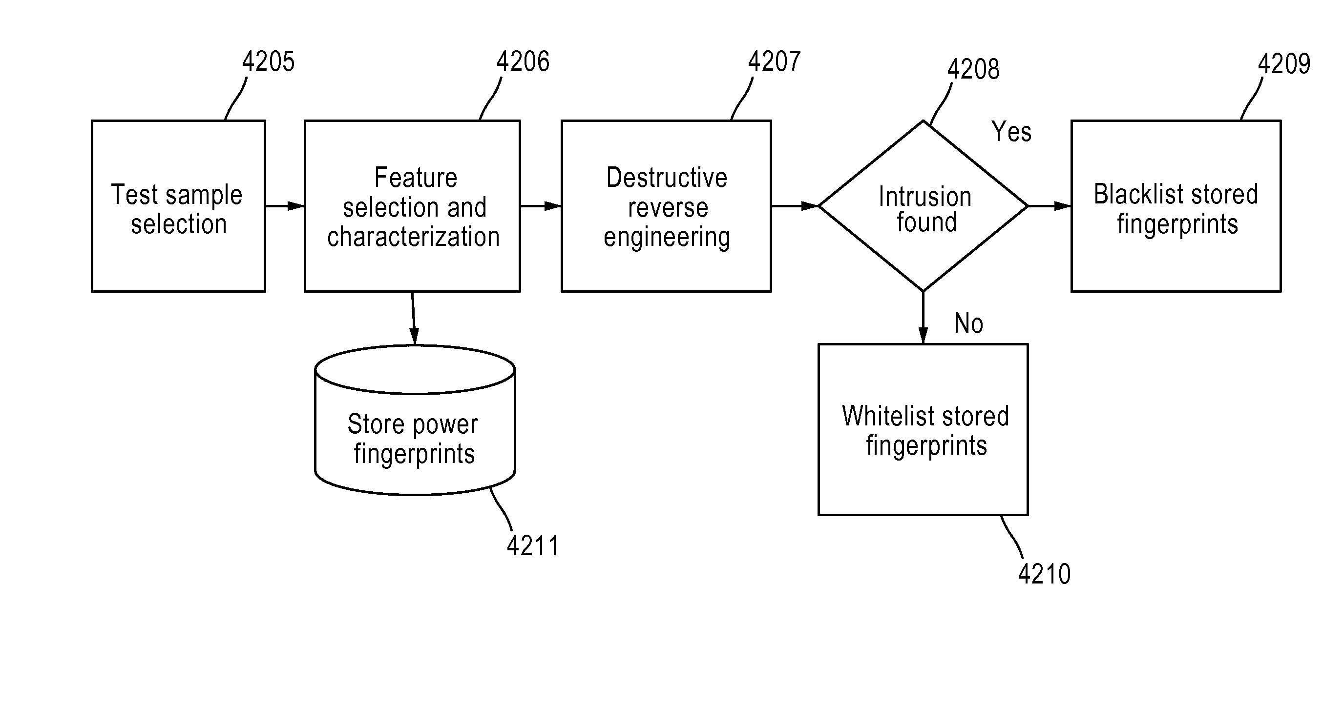
Without this automatic approach, it would take too long to characterize and extract the unique signatures from complex systems (i.e. commercial systems) to be used in power fingerprinting.
This is a relatively risky approach, because a valid execution state can be reached that has not been characterized and, hence, is flagged as an anomaly.
Fortunately, most of the elements necessary for the scaffolds overlap in functionality with the traditional scaffolds for
automatic testing (e.g. unit, integration, and
system testing), adding only a little hit of extra work.
There is no known effective procedure to determine the optimal discriminatory features for a given problem.
In practical systems, however, this is not feasible and a finite, practical PFA level must be determined.
It is important to note, however, that even if a potential attacker acquires the signatures, it would be still very difficult to match the signatures perfectly while carrying on malicious behavior.
The main challenge in PFP signature updating is
authentication (i.e. making sure the sender is an authorized entity and that the signature itself is correct and has not been tampered with or altered in any way).
For example, if not properly authenticated, the update process can be disrupted by a man-in-the-middle
attack.
It is important to note that the solutions here described are not intended to prevent attackers from carrying on side channel attacks against our target systems.
In the event the integrity of the execution status cannot be validated or authenticated, this response may prevent access to certain critical resources to prevent the target system from being damaged, exploited, or its information from being leaked.
For example, affected devices may be temporarily disabled by shutting down, or resetting or preventing operation / computation.
In the case of an attacker breaching the system, this response may prevent the device from further operation at the first sign of unauthorized execution and prevent the attacker from installing a permanent presence, such as a
back door.
The PFP system may trigger on execution violations.
Unsupervised learning is more vulnerable to evasion attempts and it opens the possibility of the attacker retraining the PFP detectors into thinking the
attack itself is part of the normal operation.
The supervised approach in PFP, however, requires heavier investments during characterization.
Increasing the time-bandwidth product allows observing the intended
signal for a longer time and reduces the accuracy on the estimates.
The more traces from the execution of a target module that are combined, the smaller the variance of the resulting estimates, hence, the smaller the chances of making a classification error.
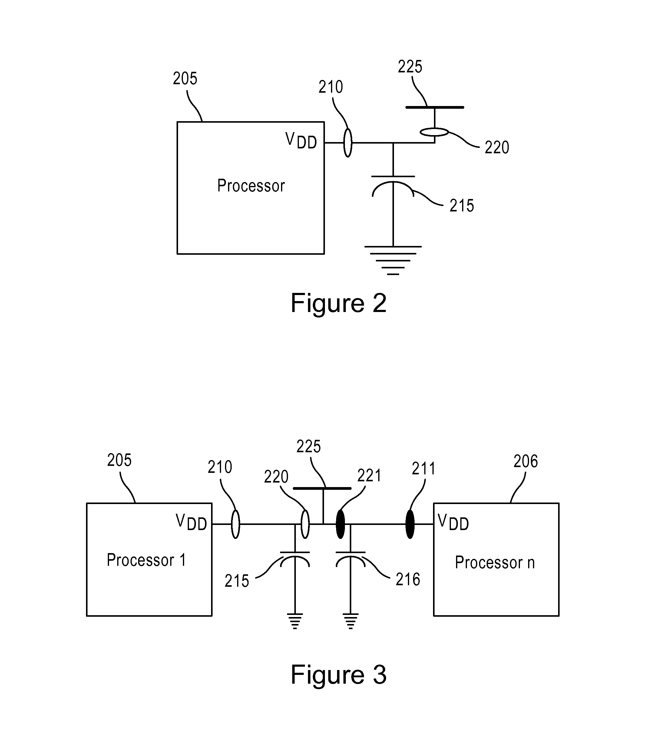
Connecting the harnesses may require small modifications to the deployed (untrusted) device to
expose power rails or access test points.
With this information, a PFP monitor can identify when a specific component is being stressed and likely to fail, which presents a strong indication of counterfeit elements.
Industrial control and
SCADA systems provide a great application for this approach due to the monitoring of multiple
processing modules that are distributed in relatively close spatial proximity but in potentially noisy environments.

