
High band excitation signal generation

a high-band excitation and signal technology, applied in the field of high-band excitation signal generation, can solve the problems of introducing perceptually significant distortion, time-domain coders may fail to retain high quality and robust performance, and many celp coding systems operating at low bit rate suffer from perceptually significant distortion characterized as nois

Active Publication Date: 2015-11-05
QUALCOMM INC
View PDF31 Cites 35 Cited by
  • Summary
  • Abstract
  • Description
  • Claims
  • Application Information

AI Technical Summary

Benefits of technology

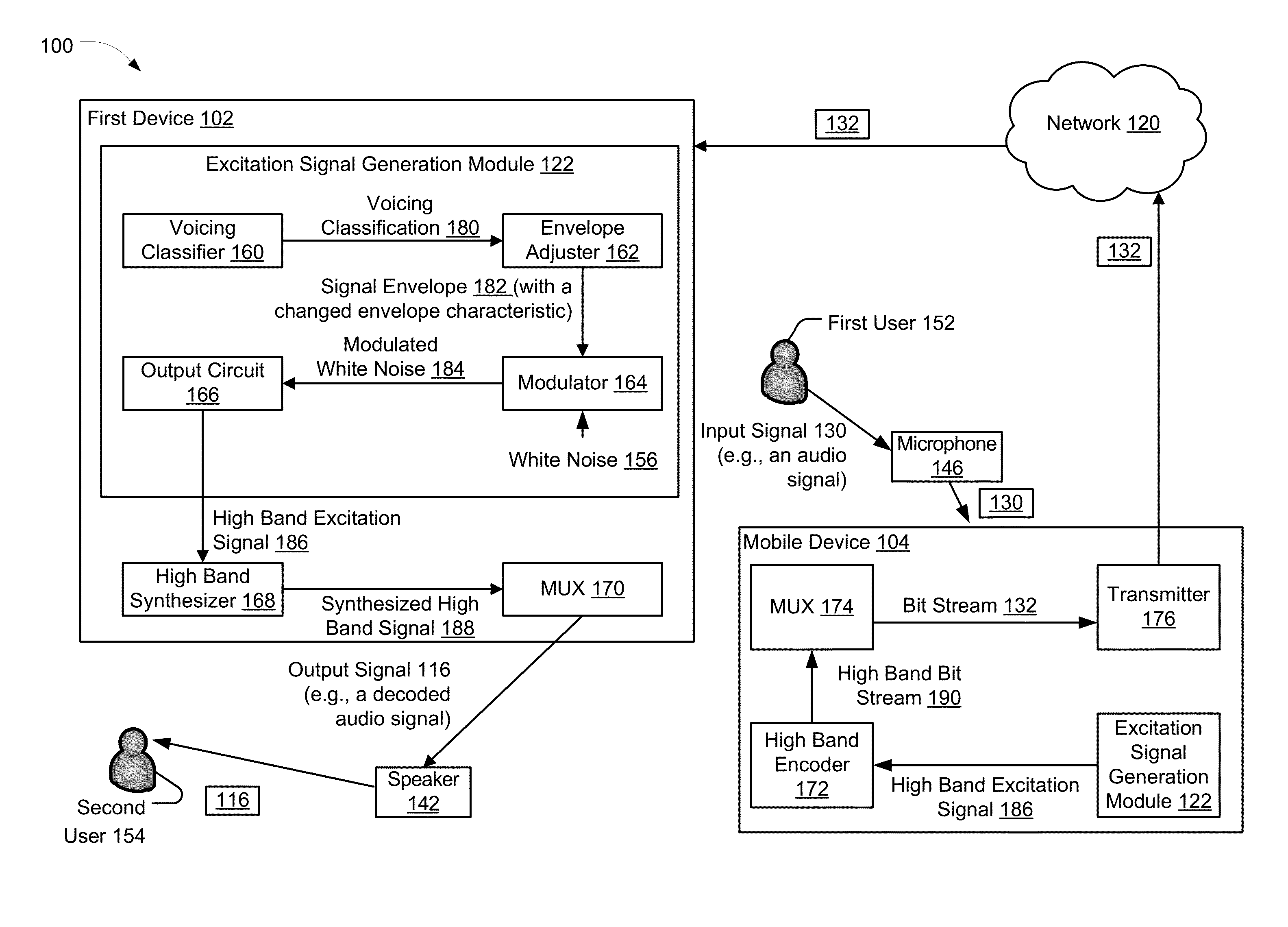
The patent describes a system and method for generating high-quality audio signals. It uses a voicing classification system to determine the type of audio signal, such as strong or weak voicing, and adjusts the envelope of the signal accordingly. This allows for a smooth and unvoiced sounding output signal to be generated. The system can also modulate a white noise signal based on the controlled envelope to create a high-band excitation signal. The technical effect of this patent is to provide a more efficient and effective way to generate high-quality audio signals.

Problems solved by technology

The challenge is to retain high voice quality of the decoded speech while achieving the target compression factor.
At low bit rates (e.g., 4 kbps and below), time-domain coders may fail to retain high quality and robust performance due to the limited number of available bits.
Hence, many CELP coding systems operating at low bit rates suffer from perceptually significant distortion characterized as noise.
Although LP vocoders provide reasonable performance generally, they may introduce perceptually significant distortion, characterized as buzz.
When the low band residual is sparsely coded with pulses, the high band excitation signal generated from the sparsely coded residual may result in artifacts in unvoiced regions of the high band.

Method used


Image

  • High band excitation signal generation
  • High band excitation signal generation
  • High band excitation signal generation

Examples


Embodiment Construction

[0036]The principles described herein may be applied, for example, to a headset, a handset, or other audio device that is configured to perform high band excitation signal generation. Unless expressly limited by its context, the term “signal” is used herein to indicate any of its ordinary meanings, including a state of a memory location (or set of memory locations) as expressed on a wire, bus, or other transmission medium. Unless expressly limited by its context, the term “generating” is used herein to indicate any of its ordinary meanings, such as computing or otherwise producing. Unless expressly limited by its context, the term “calculating” is used herein to indicate any of its ordinary meanings, such as computing, evaluating, smoothing, and / or selecting from a plurality of values. Unless expressly limited by its context, the term “obtaining” is used to indicate any of its ordinary meanings, such as calculating, deriving, receiving (e.g., from another component, block or device)...


PUM


Abstract

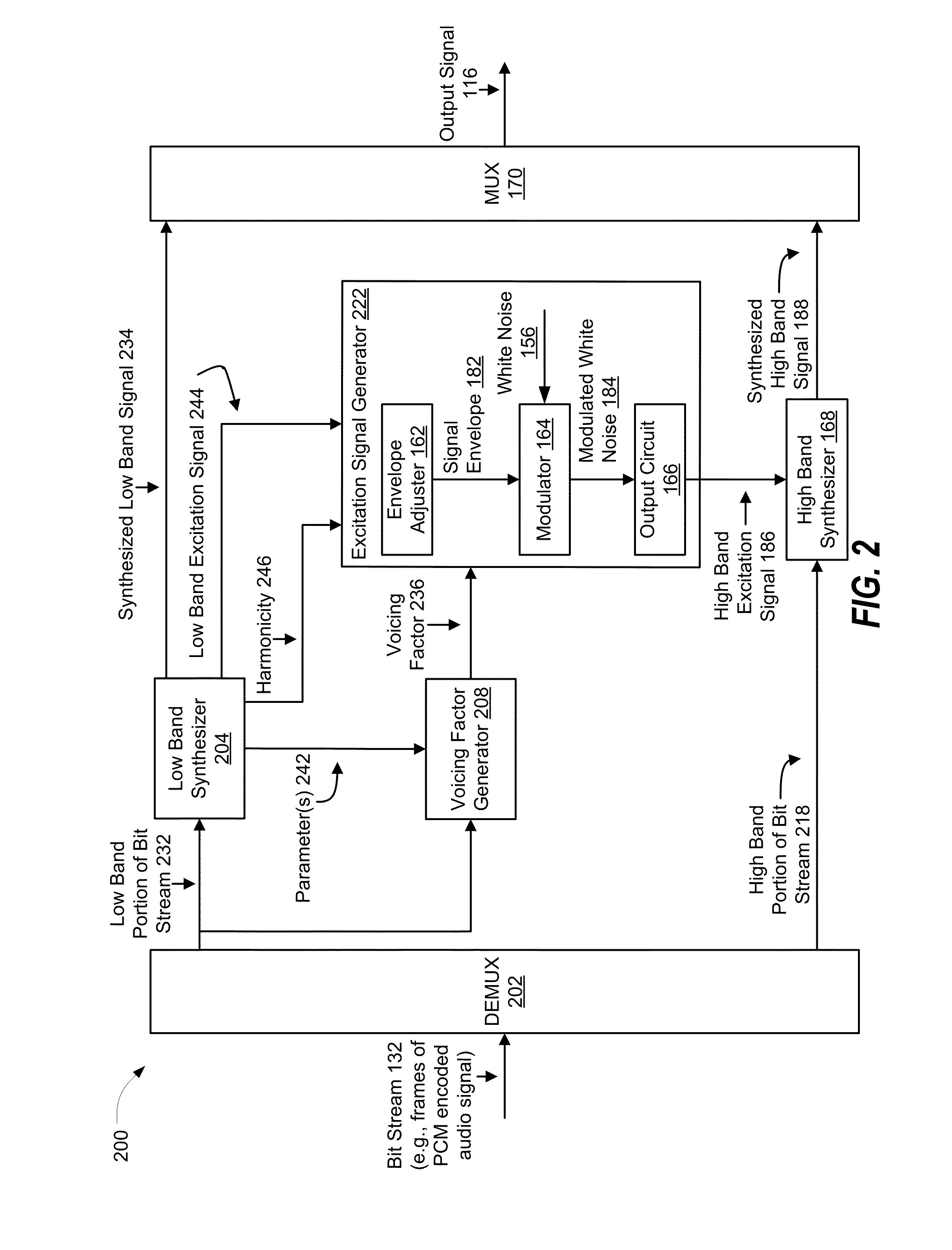
A particular method includes determining, at a device, a voicing classification of an input signal. The input signal corresponds to an audio signal. The method also includes controlling an amount of an envelope of a representation of the input signal based on the voicing classification. The method further includes modulating a white noise signal based on the controlled amount of the envelope. The method also includes generating a high band excitation signal based on the modulated white noise signal.

Description

I. FIELD[0001]The present disclosure is generally related to high band excitation signal generation.II. DESCRIPTION OF RELATED ART[0002]Advances in technology have resulted in smaller and more powerful computing devices. For example, there currently exist a variety of portable personal computing devices, including wireless computing devices, such as portable wireless telephones, personal digital assistants (PDAs), and paging devices that are small, lightweight, and easily carried by users. More specifically, portable wireless telephones, such as cellular telephones and Internet Protocol (IP) telephones, can communicate voice and data packets over wireless networks. Further, many such wireless telephones include other types of devices that are incorporated therein. For example, a wireless telephone can also include a digital still camera, a digital video camera, a digital recorder, and an audio file player.[0003]Transmission of voice by digital techniques is widespread, particularly ...

Claims


Application Information

Patent Timeline
Patent Type & Authority Applications(United States)
IPC IPC(8): G10L19/08
CPCG10L19/08G10L19/24G10L21/0208
Inventor RAMADAS, PRAVIN KUMARSINDER, DANIEL J.VILLETTE, STEPHANE PIERRERAJENDRAN, VIVEK
Owner QUALCOMM INC
Learn More