Converter circuit with power factor correction

a converter circuit and power factor technology, applied in the field of power converters, can solve the problems of low converting efficiency, large volume of storage units, bad current harmonic, etc., and achieve the effects of reducing voltage stress, avoiding breaking an output capacitor, and increasing ac input voltag

Active Publication Date: 2015-11-05
LITE ON ELECTRONICS (GUANGZHOU) LTD +1
View PDF2 Cites 7 Cited by
  • Summary
  • Abstract
  • Description
  • Claims
  • Application Information

AI Technical Summary

Benefits of technology

[0007]Therefore, the present invention is to provide a converter circuit with power factor correction, in particular to a bridgeless design. The converter circuit avoids breaking an output capacitor when AC input voltage is over high, and increases a region of the AC input voltage. Thus, the converter circuit can reduce voltage stress, increase life, increase power converting efficiency, and control input inrush current, and further curb an arc that occurs when the power is plugged or unplugged.
[0008]In one embodiment of the present disclosure, the zero crossing distortion can be cancelled by a coupling effect between inductors, to decrease the total harmonic distortion and increase the power factor.
[0011]To sum up, in the converter circuit with power factor correction provided by the present disclosure, when the bidirectional AC switch circuit is on-state, at least one of the first energy storing circuit and the second energy storing circuit is charged by the AC input current and then energy is stored with magnetic flux form; when the bidirectional AC switch circuit is off-state, at least one of the first energy storing circuit and the second energy storing circuit releases the energy to the output circuit. Therefore, the converter circuit avoids breaking an output capacitor when AC input voltage is over high, and increases a region of the AC input voltage. In addition, the converter circuit can reduce the voltage stress, increase the life, increase the power converting efficiency, and control the input inrush current. Furthermore, the converter circuit with power factor correction further curbs the arc that occurs when the power is plugged or unplugged.

Problems solved by technology

Although each of the two types have advantages, there still exists the defect of bad current harmonic, low converting efficiency, big volume of the storage unit, or complicated way of control.
The power factor corrector including the bridge converter has become the main loss of high efficiency AC-DC power converter due to the voltage drop of the high forward-conduction voltage on the converting diode.
However, the high output voltage outputted by the traditional boost bridgeless PFC causes the rear stage DC-DC power converter to need to endure more high voltage stress and extra circuit to control the input inrush current, so the problem in administration and increased cost emerges.
However, there still exists serious problems such as zero crossing distortion (ZCS) or dead zone, and also emerging is a total harmonic distortion and low power factor.

Method used


Image

  • Converter circuit with power factor correction
  • Converter circuit with power factor correction
  • Converter circuit with power factor correction

Examples


Embodiment Construction

[0026]The topology of the power factor correction develops into the bridgeless design. The bridgeless power factor corrector is the commonly-shared circuit, and replaces the way of traditional bridge converter and power factor correction being separated, so as to reduce the forward-conduction voltage of the bridge converter to increase the efficiency of the power supply.

[0027]Before the present invention is described in greater detail, it should be noted that like elements are denoted by the same reference numerals throughout the disclosure. As used herein, the term “or” includes any and all combinations of one or more of the associated listed items.

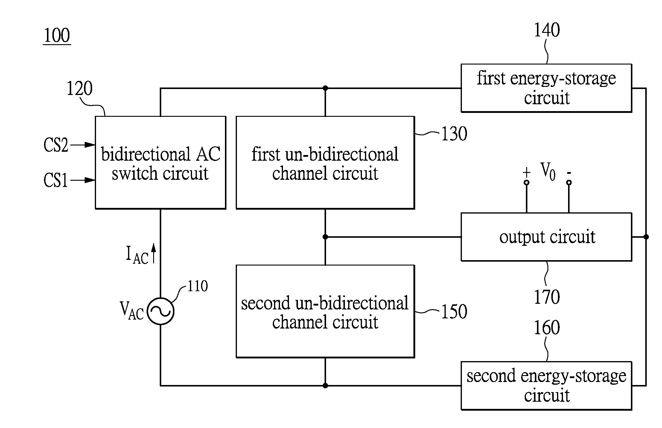
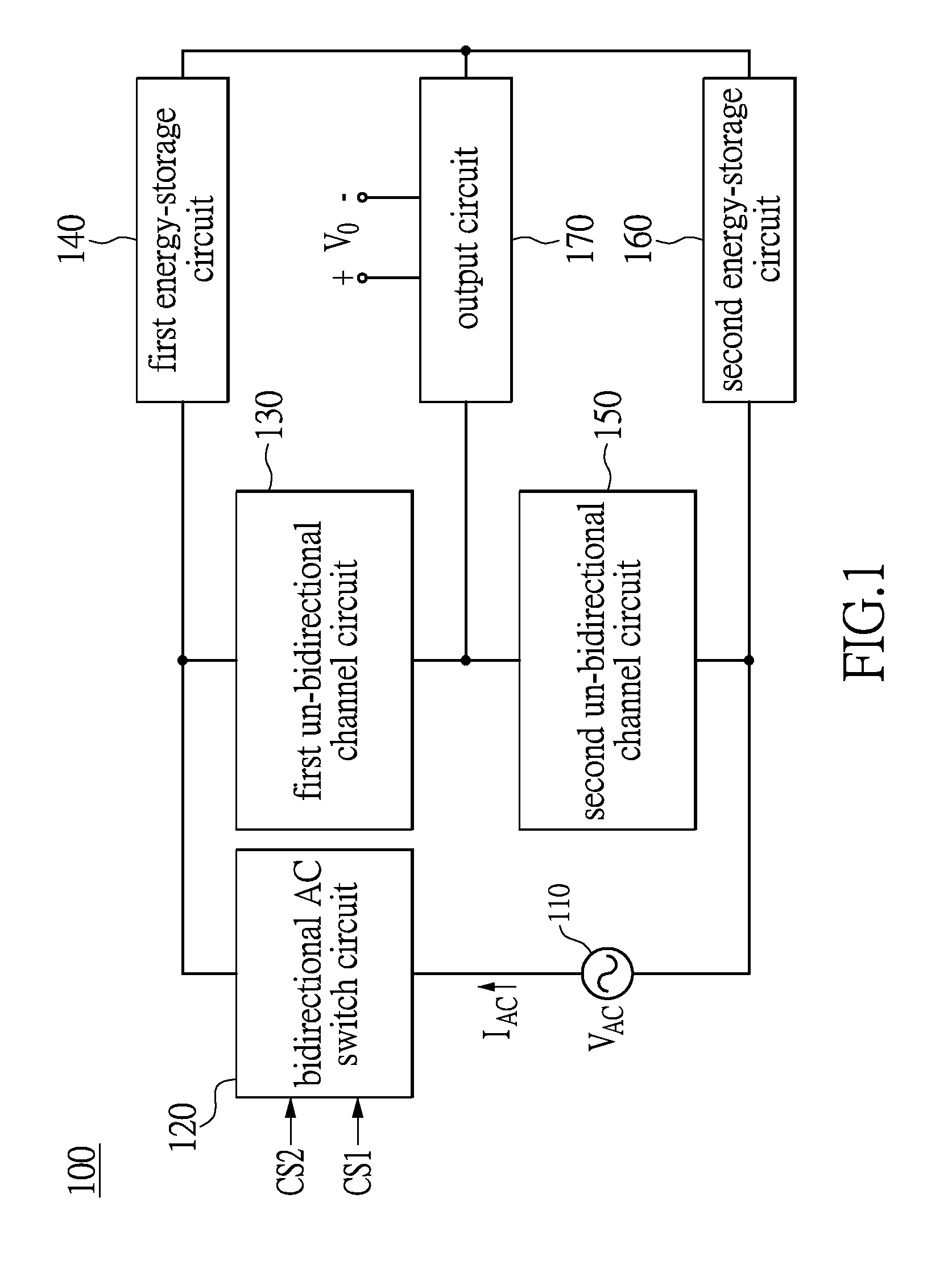
[0028]Referring to FIG. 1, the present disclosure discloses a converter circuit 100 with power factor correction configured for converting an AC input voltage VAC into a DC output voltage VO (e.g., AC-DC converting). Compared with the conventional knowledge, the present disclosure saves a full-bridge converting diode (the diode will gene...


PUM


Abstract

A converter circuit with power factor correction comprises an alternative current (AC) voltage source, a bidirectional AC switch circuit, a first un-bidirectional channel circuit, a second un-bidirectional channel circuit, a first energy storing circuit, a second energy storing circuit and an output circuit. When the bidirectional AC switch circuit is on-state, at least one of the first energy storing circuit and the second energy storing circuit is charged by an AC input current and then energy is stored with magnetic flux form. When the bidirectional AC switch circuit is off-state, at least one of the first energy storing circuit and the second energy storing circuit releases the energy to the output circuit.

Description

BACKGROUND[0001]1. Technical Field[0002]The present disclosure relates to a power converter, and more particularly to a converter circuit with power factor correction, which raises the power converting efficiency and controls the input inrush current.[0003]2. Description of Related Art[0004]Recently, the switch power supply industry is growing rapidly, because it plays a most important role in the electronic apparatus. The switch power supply has the advantages of stability, simplicity, and efficiency when compared with the traditional power supply. When attention is paid to environmental protection and the energy saving, the trend about improvement of the alternating current (AC) isolated-switch power supply appears to be going to the topology of synchronous converting controlling in the secondary side and the power factor correction in the primary side.[0005]The DC voltage is utilized in many electronic apparatuses. Since the supply terminal of Mains is the AC voltage, the electro...

Claims


Application Information

Patent Timeline
Patent Type & Authority Applications(United States)
IPC IPC(8): H02M1/42H02M7/12
CPCH02M7/12H02M1/4225H02M1/4208H02M1/44Y02B70/10
Inventor HUANG, CHIN-CHUANCHEN, WEI-RU
Owner LITE ON ELECTRONICS (GUANGZHOU) LTD
Why Eureka
Try Eureka