

Stirrer
- Summary
- Abstract
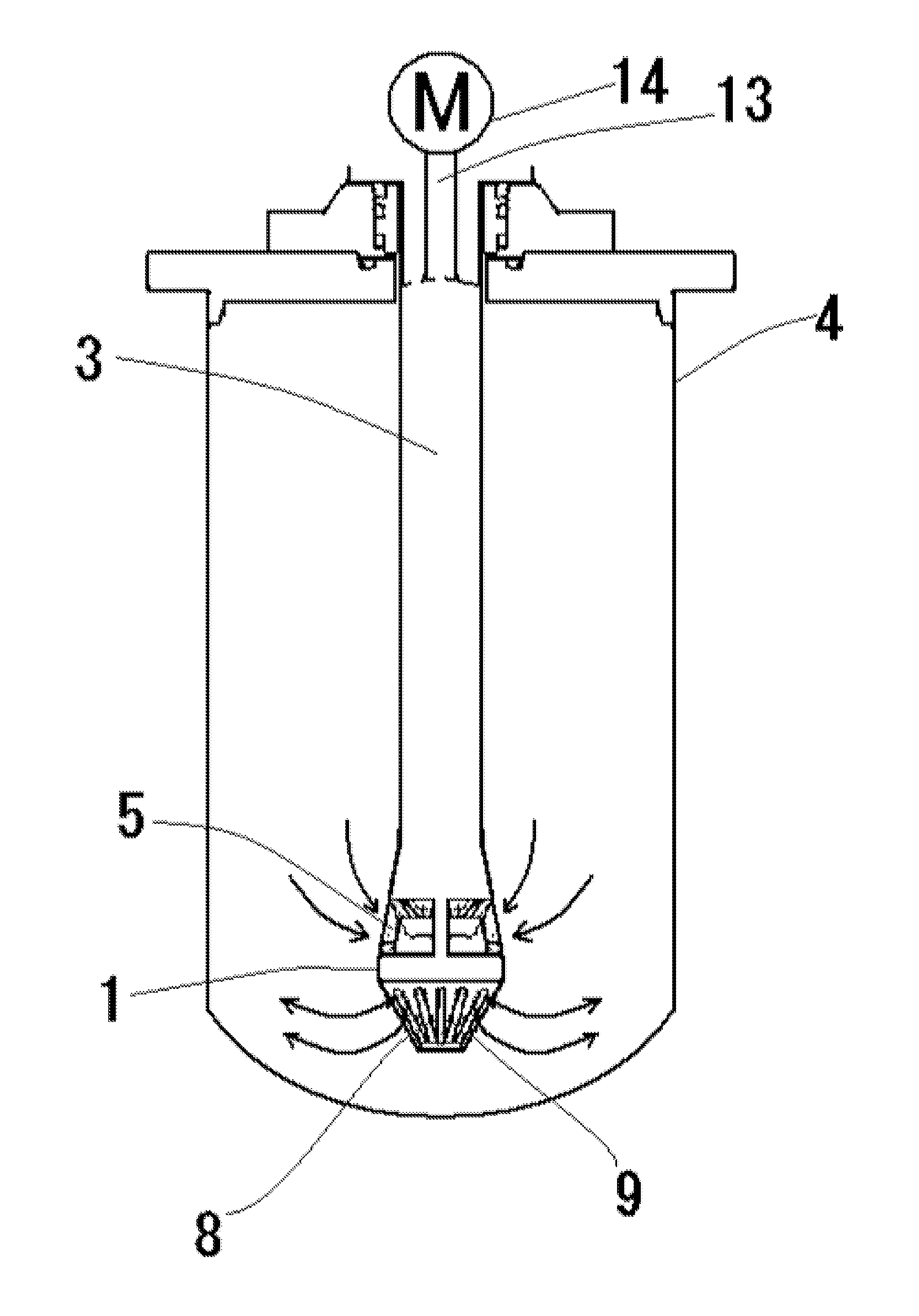
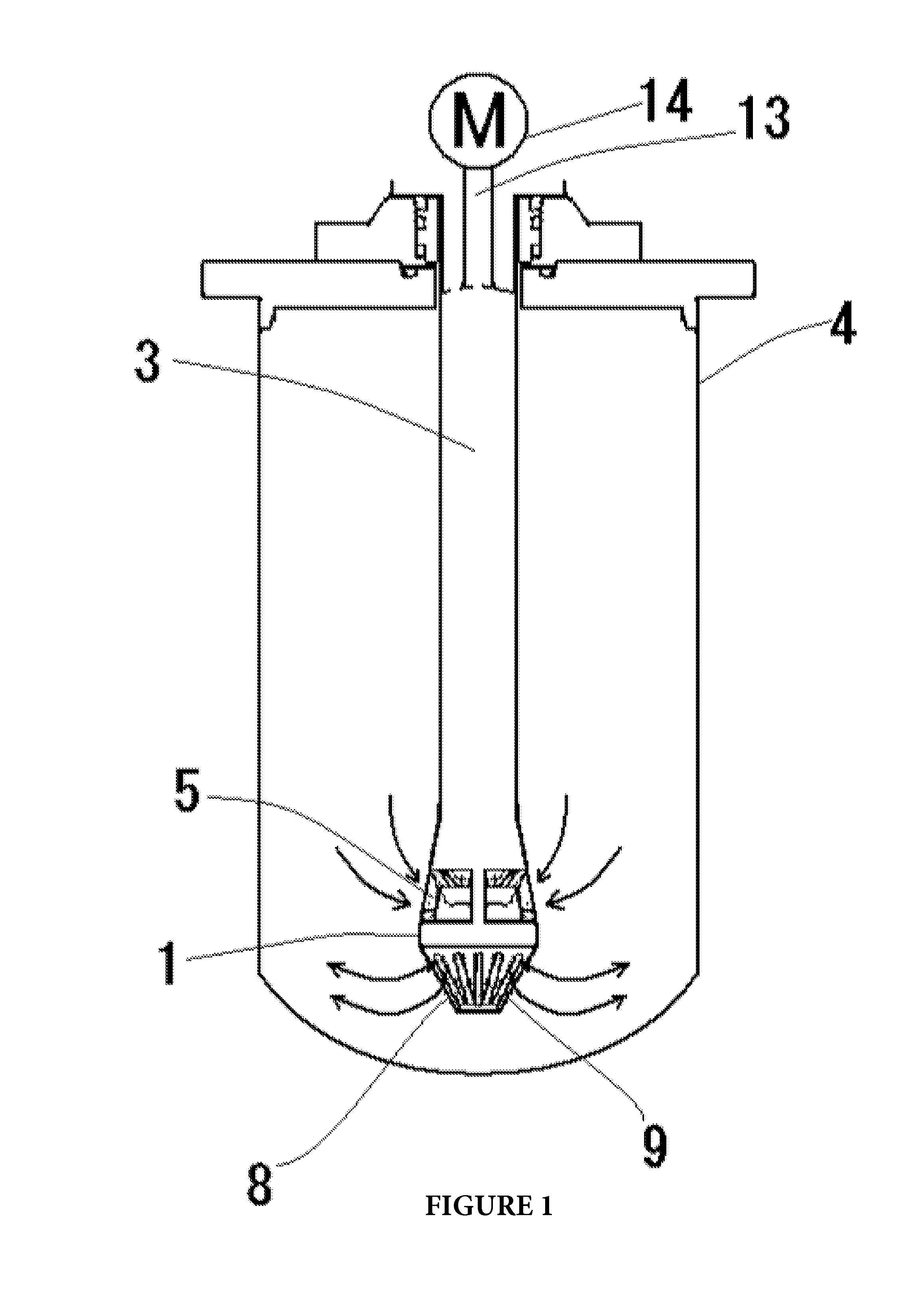
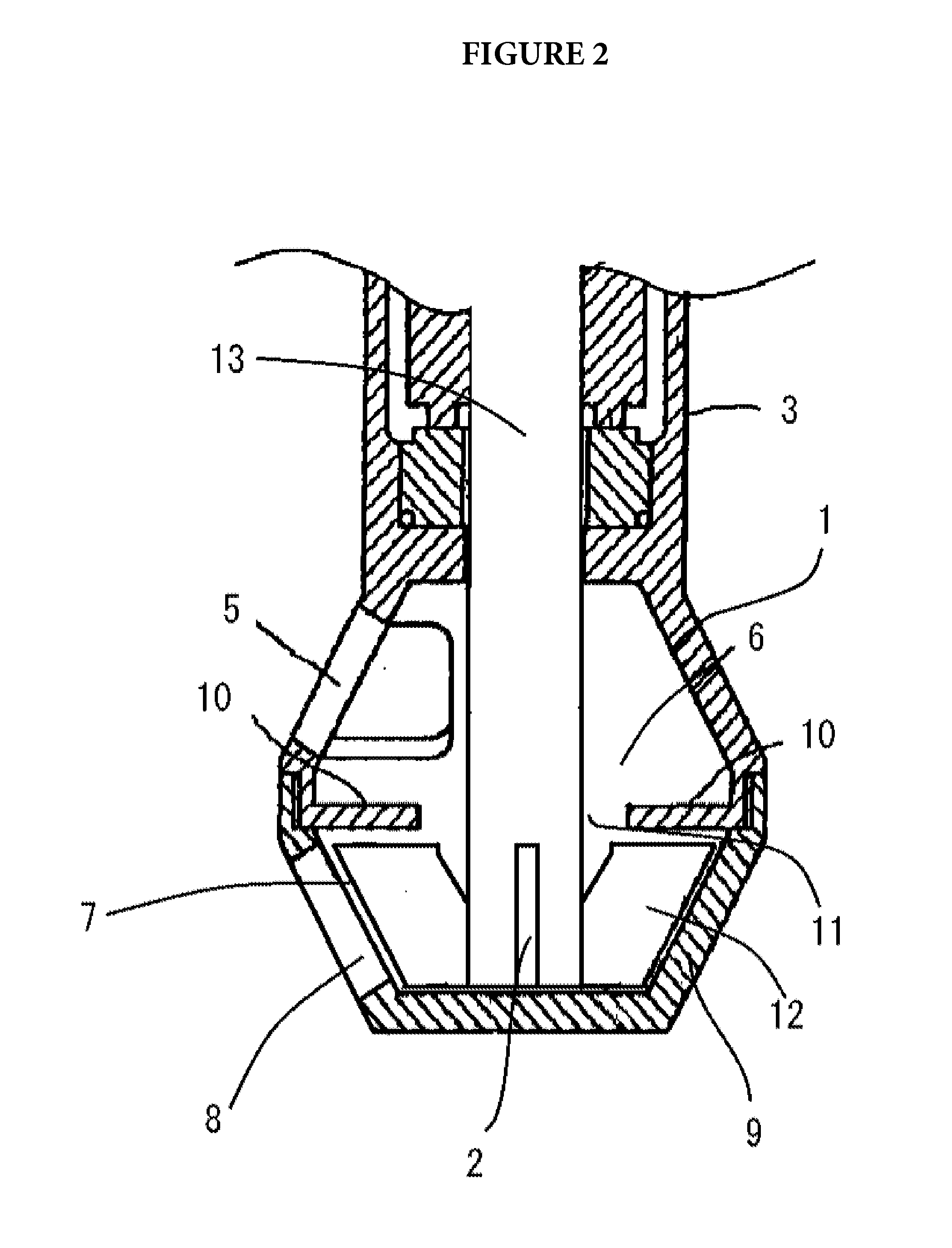
- Description
- Claims
- Application Information
AI Technical Summary
Benefits of technology
Problems solved by technology
Method used
Image

Examples
examples
[0130]Hereunder, the present invention will be explained further specifically by showing Examples. However, the present invention is not limited to the following Examples.
Measurement of the Particle Diameter Distribution:
[0131]Each of the particle diameter distribution in Examples is measured by MT-3300 (manufactured by Nikkiso Co., Ltd.). Pure water was used as the solvent for measurement; and the refractive index of the particle was 1.81, and the refractive index of the solvent was 1.33. The results were obtained in terms of the volume distribution.
[0132]In Examples 1, by using the stirrer according to the first embodiment of the present invention (FIG. 1 and FIG. 2), the emulsification experiment of liquid paraffin and pure water was carried out in accordance with the flow diagram shown in FIG. 10(A). The formulation used in the emulsification experiment was a mixture of 29.4% by weight of liquid paraffin, 68.6% by weight of pure water, and as the emulsification agents, a mixture...
PUM
| Property | Measurement | Unit |
|---|---|---|
| Speed | aaaaa | aaaaa |
| Speed | aaaaa | aaaaa |
| Speed | aaaaa | aaaaa |
Abstract
Description
Claims
Application Information