

Antenna device
a technology of antenna device and antenna device, which is applied in the structure of radiating elements, solid-state devices, resonance antennas, etc., can solve the problems of difficult to vary the directivity of radio waves, increase etc., and achieve the effect of increasing the cost of antenna device and considering cos
- Summary
- Abstract
- Description
- Claims
- Application Information
AI Technical Summary
Benefits of technology
Problems solved by technology
Method used
Image

Examples
first embodiment
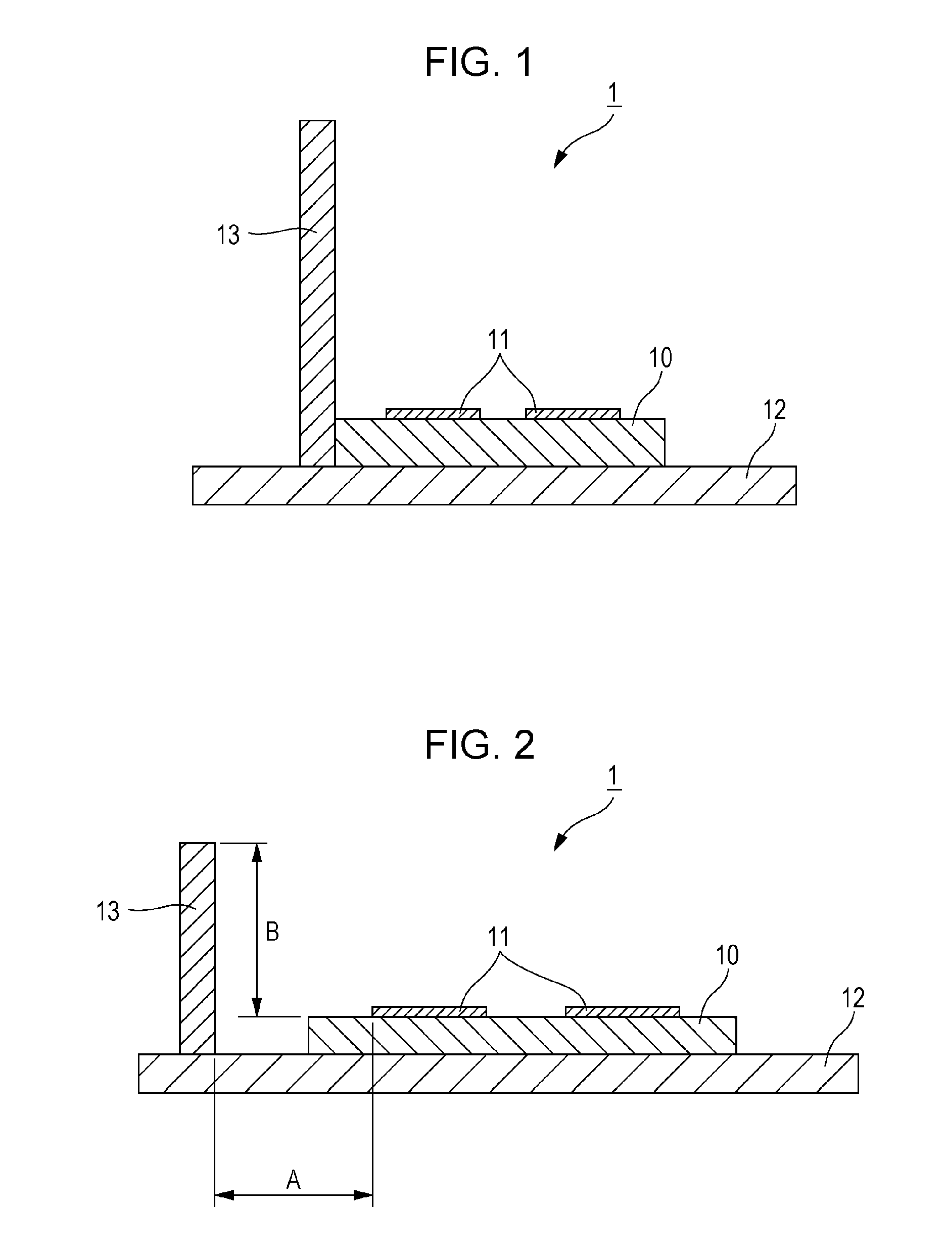
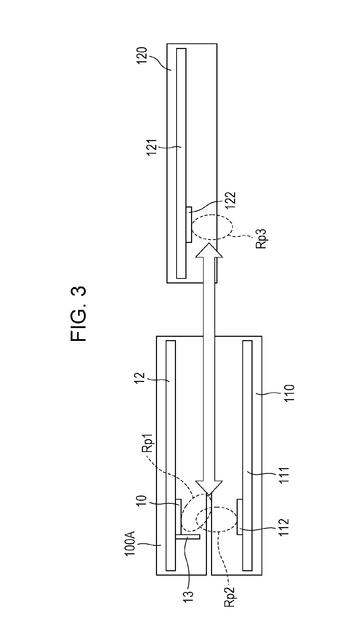
[0048]FIG. 1 is a cross-sectional view illustrating a configuration of an antenna device 1 according to a first embodiment. In FIG. 1, the antenna device 1 in this embodiment includes a wireless module 10, a multi-layer wiring module substrate (mounting substrate) 12, and a metal plate 13. The wireless module 10 includes an antenna element 11 that operates in a microwave band or a millimeter-wave band on an upper surface thereof. The multi-layer wiring module substrate (mounting substrate) 12 has the wireless module 10 thereon. The metal plate 13 is disposed in a vertical position near the antenna element 11.
[0049]The antenna element 11 includes a transmitting antenna element and a receiving antenna element. The antenna element 11 illustrated in FIG. 1 is the receiving antenna element, for example. The wireless module 10 includes an IC (Integrated Circuit) for wireless communication (not illustrated) that transmits (radiates) and receives radio waves through the antenna element 11. ...
second embodiment
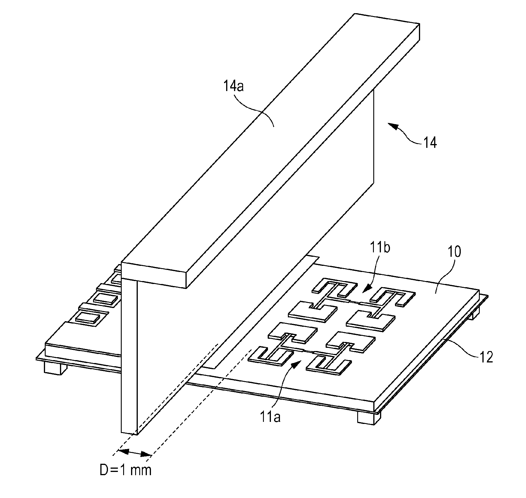
[0053]FIG. 4 is a cross-sectional view illustrating a configuration of an antenna device according to a second embodiment. FIG. 5 is a perspective view illustrating an exterior of the antenna device according to the second embodiment. The components in FIG. 4 and FIG. 5 that are the same as those in FIG. 1 are assigned the same reference numerals as those in FIG. 1, and description thereof is omitted. An antenna device 2 according to this embodiment includes a metal plate 14 including a front end portion 14a that is bent at a right angle over a part of the antenna element 11. The front end portion 14a may be bent at any angle other than the right angle as long as the front end portion 14a is bent over the part of the antenna element 11. As illustrated in FIG. 5, the antenna element 11 mounted on the wireless module 10 includes a transmitting antenna element 11b and a receiving antenna element 11a. The metal plate 14 is separated from the antenna elements 11a and 11b by 1 mm.
[0054]FI...
third embodiment
[0056]FIG. 8 is a cross-sectional view illustrating a configuration of an antenna device according to a third embodiment. FIG. 9 is a top view of the antenna device in the third embodiment. The components in FIGS. 8 and 9 that are the same as those in FIG. 1 are assigned the same reference numerals as those in FIG. 1, and description thereof is omitted.
[0057]As illustrated in FIG. 8 and FIG. 9, an antenna device 3 in this embodiment includes a metal plate 17 including a portion that is bent as in the antenna device 2 in the second embodiment. Unlike the metal plate 14 of the antenna device 2 in the second embodiment, a bent portion 17a extends over an entire upper surface of the wireless module 10 diagonally relative to the wireless module 10 and has an opening 17b at a position above the antenna element 11. In the antenna device 3 including the metal plate 17, some of the radio waves from the antenna element 11 are radiated in a vertical direction through the opening 17b in the met...
PUM
 Abstract
Description
Claims
Application Information