Relay device, station side device, and communication system and communication method using relay device

Inactive Publication Date: 2015-11-12
SUMITOMO ELECTRIC IND LTD
View PDF1 Cites 7 Cited by
  • Summary
  • Abstract
  • Description
  • Claims
  • Application Information

AI Technical Summary

Benefits of technology

[0019]According to the present invention, even when upstream multiple access control is performed independently i

Problems solved by technology

In such a PON system, the larger the number of splits and

Method used


Image

  • Relay device, station side device, and communication system and communication method using relay device
  • Relay device, station side device, and communication system and communication method using relay device
  • Relay device, station side device, and communication system and communication method using relay device

Examples


first embodiment

[0248][Device Configuration, Etc., of the First Embodiment]

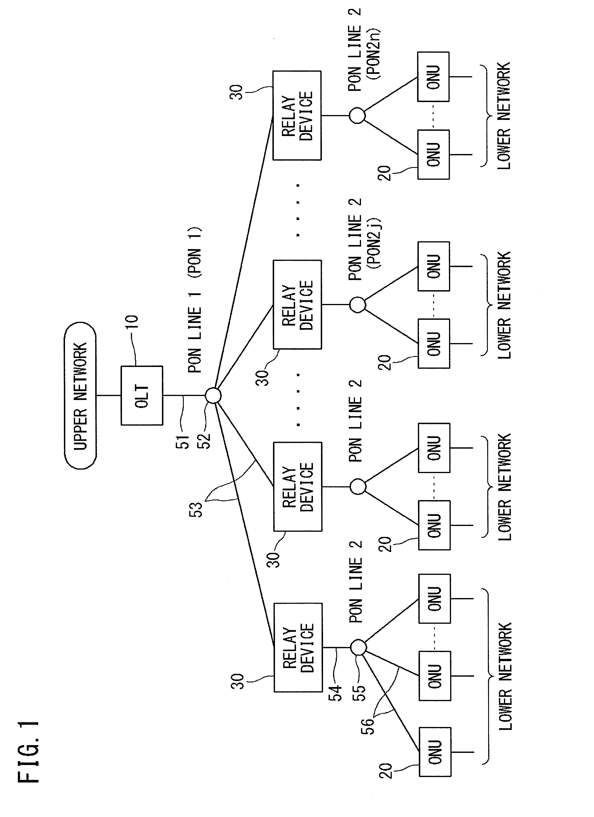
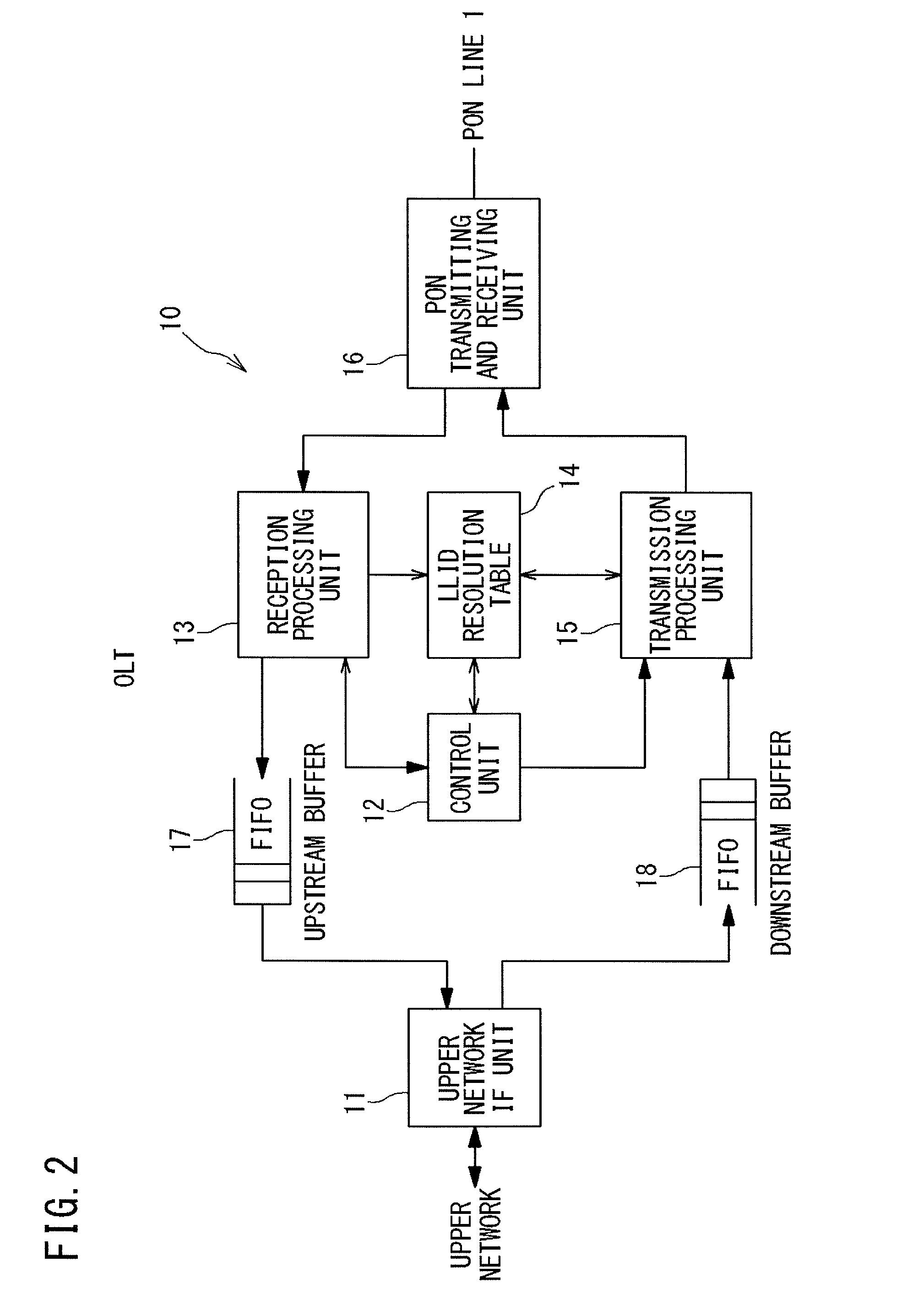
[0249]The configurations of an optical communication system, an OLT 10, and ONUs 20 according to the first embodiment are the same as those in the case of the first basic mode (see FIGS. 1 to 3).

[0250]The basic components of a relay device 30 are also the same as those of the case of the first basic mode (FIG. 4), but in the first embodiment the correspondence relationship between the logical link of a PON line 1 and the logical links of a PON line 2 is any and thus may be either “one-to-many” or “one-to-one”.

[0251][Configuration and Function of an Upstream Buffer]

[0252]FIG. 13 is an illustrative diagram of a second upstream buffer 40 for user frames which is used in the relay device 30 (the basic configuration is the same as that of FIG. 4) of the first embodiment.

[0253]As shown in FIG. 13, in the relay device 30 of the first embodiment, the second upstream buffer 40 is composed of a ring buffer capable of making a “reserva...

second embodiment

[0294][Device Configuration, Etc., of the Second Embodiment]

[0295]The configurations of an optical communication system, an OLT 10, and ONUs 20 according to the second embodiment are the same as those in the case of the first basic mode (see FIGS. 1 to 3).

[0296]The basic components of a relay device 30 are also the same as those of the case of the first basic mode (FIG. 4), but the second embodiment assumes the case in which there is a “one-to-one” correspondence relationship between the logical link of a PON line 1 and the logical links of a PON line 2.

[0297]In addition, it is assumed that the configuration of a second upstream buffer 40 for user frames which is used in the relay device 30 (the basic configuration is the same as that of FIG. 4) of the second embodiment is the same as that of the first embodiment shown in FIG. 13.

[0298][Sequence of Distributed DBA and Effect Thereof]

[0299]FIG. 16 is a diagram showing a sequence of distributed DBA of the second embodiment.

[0300]As sh...

third embodiment

[0335][Overall Configuration of a System]

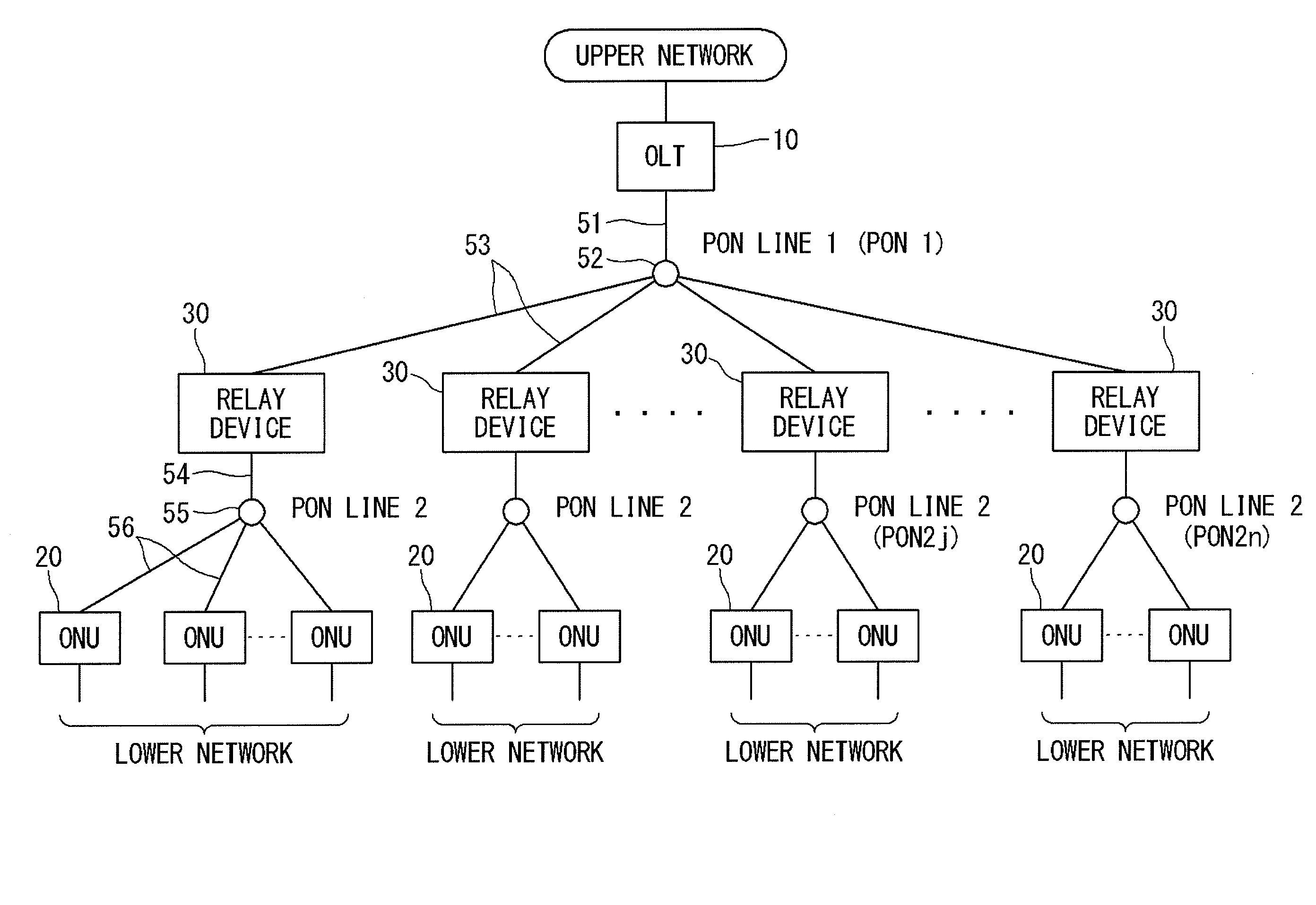
[0336]FIG. 17 is a diagram showing a connection mode of a communication system according to the third embodiment.

[0337]As shown in FIG. 17, in the communication system of the third embodiment, an upper-level network is composed of a PON (specifically, a GE-PON) using an optical fiber, and a lower-level network is composed of a CDN (Coaxial Distribution Network) using a coaxial cable (Coax).

[0338]In general, the CDN is composed of a network in which a CLT (Coax Line Terminal) which is a station side device is connected to a plurality of CNUs (Coax Network Units) which are home side devices in a one-to-many manner by split coaxial cables.

[0339]Hence, in the communication system of the third embodiment, in the lower-level network where a relay device 30 behaves as a CLT, a coaxial cable 154 is split into a plurality of branch lines 156 through a CATV splitter 155, and CNUs 120 are connected to the branch lines 156.

[0340]Therefore, an electrical ...


PUM


Abstract

A relay device of the present invention includes a relay processing unit that relays a downstream frame received by a first transmitting and receiving unit to a second transmitting and receiving unit, and relays an upstream frame received by the second transmitting and receiving unit to the first transmitting and receiving unit; and a control unit that follows upstream multiple access control performed by a station side device in a first line, for transmission of the upstream frame to be transmitted by the first transmitting and receiving unit to the station side device, and independently performs upstream multiple access control for reception of the upstream frame received by the second transmitting and receiving unit from a home side device in a second line. The control unit reports an amount of data that the home side device in the second line will be allowed to transmit, to the station side device in the first line before the data arrives at the second transmitting and receiving unit.

Description

TECHNICAL FIELD[0001]The present invention relates to a relay device for connecting communication networks in a multi-level manner that perform multiple access control of a polling scheme, e.g., PONs (Passive Optical Networks), a station side device used in a communication network on the upper-level side, and a communication system and a communication method using the relay device.BACKGROUND ART[0002]A PON system is an optical communication system that performs optical splitting in a P2MP (Point to Multi Point) connection mode, with no power and includes a station side device; a single-core optical fiber network where an optical fiber connected to the station side device is split into a plurality of optical fibers through an optical coupler; and home side devices connected to ends of the split optical fibers, respectively.[0003]In the PON system, NRZ (Non-Return to Zero) optical signals obtained by directly or externally modulating a light source such as a semiconductor laser are tr...

Claims


Application Information

Patent Timeline
IPC IPC(8): H04B10/29H04B10/27
CPCH04B10/27H04B10/29H04B10/272H04L12/4625H04Q11/0067H04Q2011/0086
Inventor YAMASHITA, KAZUHISAINOUE, TORU
Owner SUMITOMO ELECTRIC IND LTD
Why Eureka
Try Eureka