Camera module

Active Publication Date: 2015-11-12
LG INNOTEK CO LTD
View PDF1 Cites 8 Cited by
  • Summary
  • Abstract
  • Description
  • Claims
  • Application Information

AI Technical Summary

Benefits of technology

[0018]It is possible to protect a drawback that an optical axis between an image sensor and a lens module is not arranged to be concentric or is arranged to be concentric but the image sensor and the lens module are assembled under a

Problems solved by technology

By the way, the camera module may not be operated accurately when an optical axis between an image sensor fixed on a printed circuit board and a lens m

Method used


Image

  • Camera module
  • Camera module

Examples


Example

[0021]Hereafter, an embodiment of the present invention will be described with reference to the accompanying drawings.

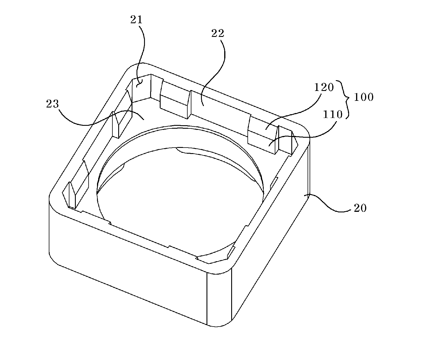
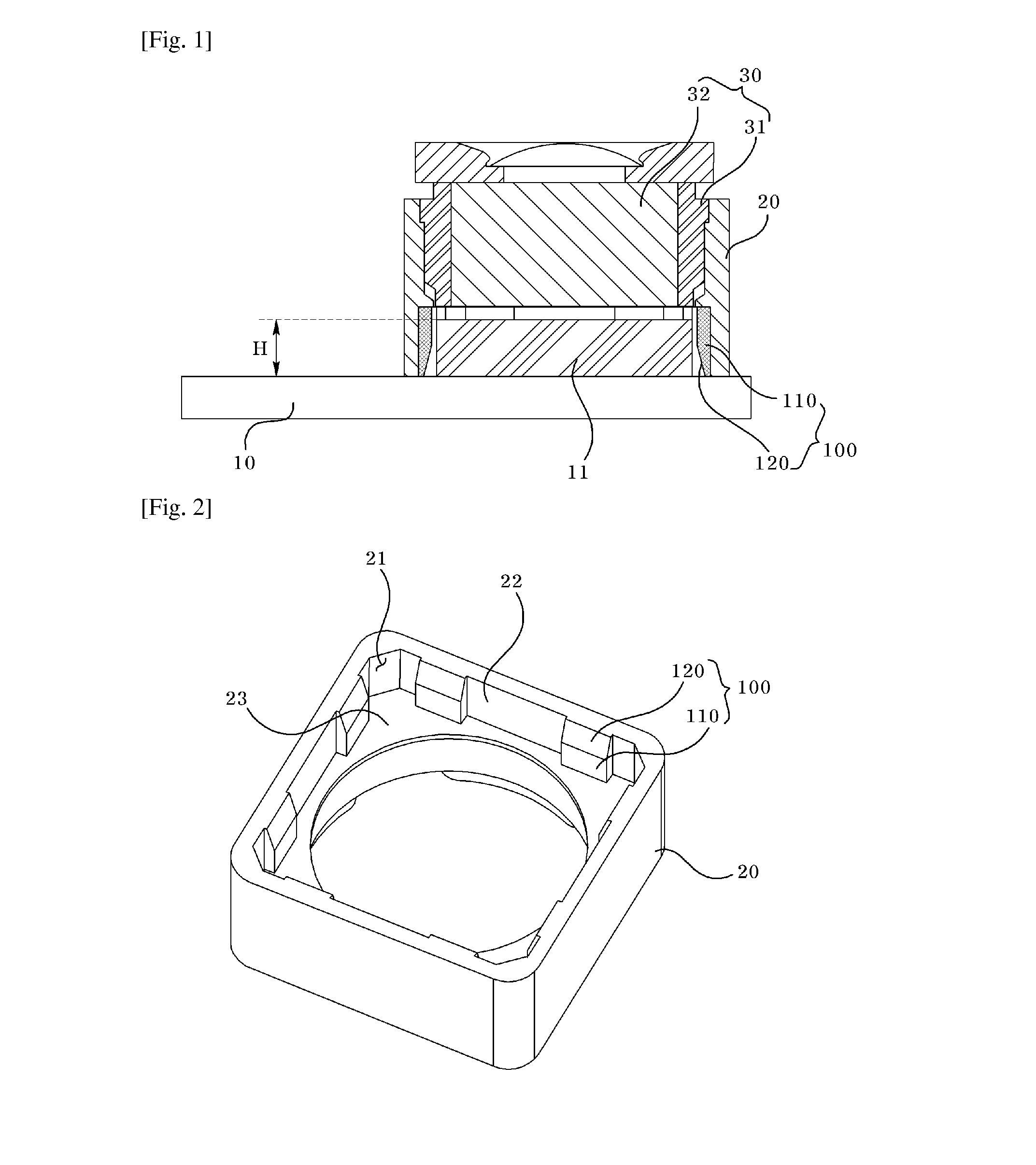
[0022]FIG. 1 is a cross-sectional perspective view of a camera module according to an embodiment of the present invention, and FIG. 2 is a perspective view of a holder member according to an embodiment of the present invention.

[0023]A camera module according to an embodiment of the present invention, as shown in FIG. 1, includes a printed circuit board (10), a holder member (20), a lens module (30) and a guide unit (100).

[0024]Image information can be read through an image sensor installed very close to the center of the printed circuit board. The image sensor (11) can be mounted on a surface of the printed circuit board (10) using a solder ball or a wire bonding, and the like.

[0025]A holder member (20) can be inserted and coupled on an upper side of the printed circuit board (10), as shown in FIG. 1, wherein the image sensor (11) can be inserted and coupled at one s...


PUM


Abstract

The camera module according to an embodiment of the present invention including: a printed circuit board on which
Nan image sensor is mounted; a holder member installed on the printed circuit board; a lens module located in the holder member; and a guide unit formed protruding from the surface of the holder member opposite to the image sensor.

Description

TECHNICAL FIELD[0001]The invention relates to camera module.BACKGROUND ART[0002]Recently, demands of using a miniature camera module have been greatly increased due to wide application areas including various multimedia areas such as tablet personal computer, camera phone, PDA, smart phone, and including a further use for image input equipments such as CCTV or information terminals of a video tape recorder. More particularly, the smart phone has been shown a recent trend that requires a development for a tiny camera module due to increased demand for consumer's preferred compact design.[0003]The camera module is manufactured using an image sensor such as CCD (Charge Coupled Device) or CMOS (Complementary Metal Oxide Semiconductor), wherein An image is transferred to display an object to a display media such as LCD display device by concentrating light hitting the object through lens inside the sensor, hereby converting the light energy into an electric energy.[0004]By the way, the c...

Claims


Application Information

Patent Timeline
IPC IPC(8): H04N5/225G03B17/02G02B7/02
CPCH04N5/2257H04N5/2252G03B17/02G02B7/02H04N5/2254H04N23/51H04N23/57H04N23/55G03B3/02G02B7/04G03B30/00G03B2217/002
Inventor KIM, HYUN JUNHA, TAE MIN
Owner LG INNOTEK CO LTD
Why Eureka
Try Eureka