Method and apparatus for reporting channel state information in wireless communication system

a wireless communication system and channel state technology, applied in the field of telecommunications equipment, can solve problems such as radio technology development, and achieve the effects of improving throughput, improving channel state information, and improving channel state information

Active Publication Date: 2015-11-12
SONY CORP
View PDF0 Cites 29 Cited by
  • Summary
  • Abstract
  • Description
  • Claims
  • Application Information

AI Technical Summary

Benefits of technology

[0012]Conveniently, the plurality of sub-band parts may have a plurality of characteristic sub-band sizes, at least a first group of the sub-band parts having a first characteristic sub-band size and a second group of the sub-band parts having a second characteristic sub-band size, the first characteristic sub-band size and second characteristic sub-band size being different, thereby facilitating reporting channel state information at different degrees of granularity for different parts of the system bandwidth. Thus within a (wide band) host carrier, the sub-band size is adaptively selected depending on fluctuation of channel quality.
[0013]This makes it possible to provide fine resolution frequency scheduling and better performance of throughput for narrowband carriers and allows an efficient MTC Virtual carrier (narrow band) operation in host carrier.
[0014]Furthermore the method facilitates the indication of the sub-band size that has been configured.

Problems solved by technology

One of the key issues to be considered in the development of radio technology is fading.

Method used


Image

  • Method and apparatus for reporting channel state information in wireless communication system
  • Method and apparatus for reporting channel state information in wireless communication system
  • Method and apparatus for reporting channel state information in wireless communication system

Examples


embodiment 1

[0102]In this embodiment, a new sub-band size is introduced in case of narrow band (e.g. 6RBs bandwidth).

[0103]A convenient and suitable size of frequency range for this narrow band sub-band is a RB (1 resource block=12*15 kHz=180 kHz), which is the baseline of resource allocation in LTE. As a result, for a virtual carrier bandwidth of 6RBs, this would give six sub-bands.

[0104]In one version of the fixed sub-band size case, this sub-band size may be defined in a table (Table 3). The benefit of fixed size and defined in specification is that there is no need for signalling.

Table 3the fixed sub-band size definition (examples)casesub-band size “k”Unit of kwideband6Resource blocksfixed sub-band (normal)1Resource blocksfixed sub-band (fine)1subcarriers

[0105]In a typical urban environment (e.g. delay profile=1000 ns), 1RB resolution might be sufficient. However, if larger delay profile (2000-5000 ns, i.e. complicated multipath case), a finer resolution might be better. As Table 3 indicate...

embodiment 2

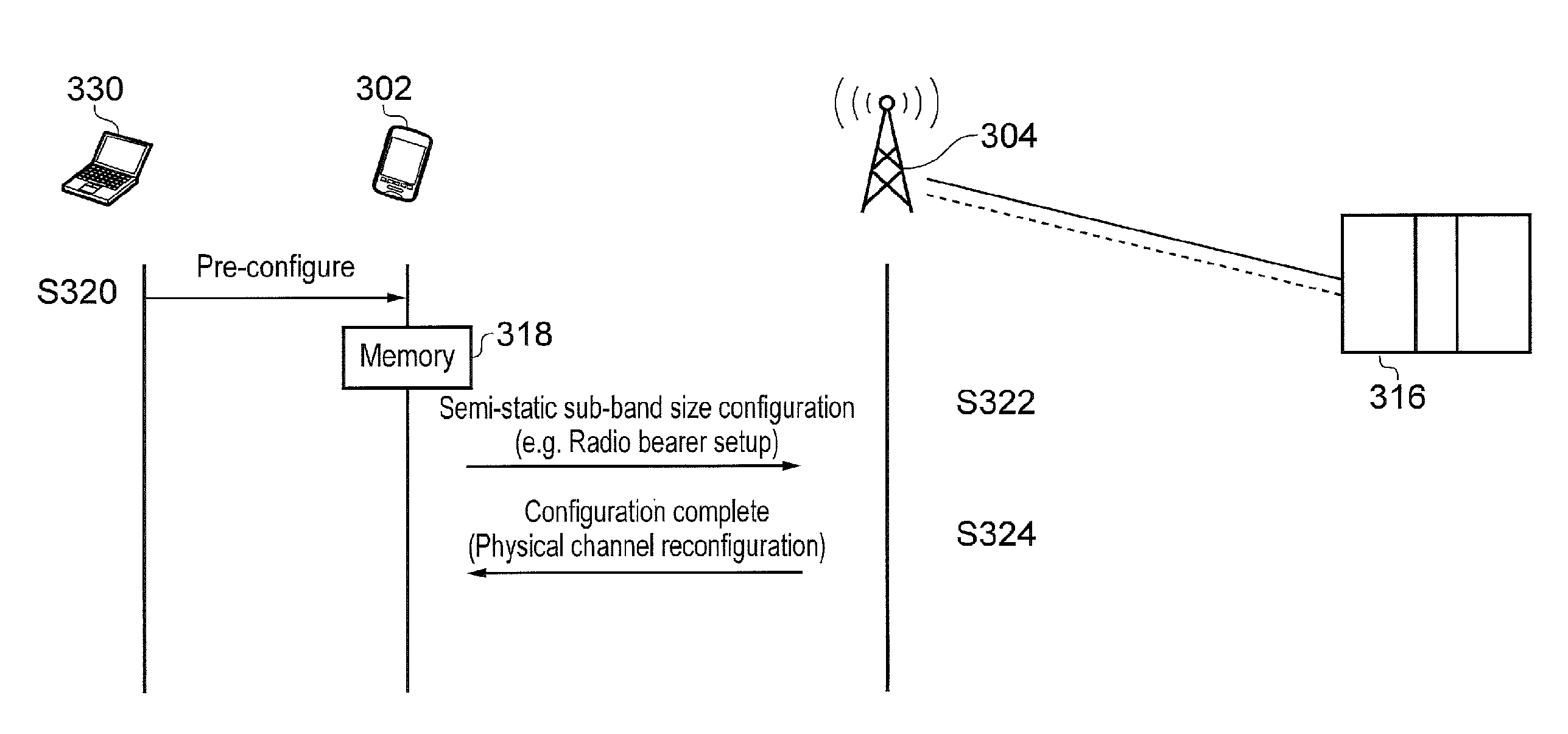
[0110]In another embodiment, a semi-static configuration may be applied to the determination of a suitable sub-band size.

[0111]Semi-static means once the sub-band size is decided, it continues to be used until the situation is changed. For example, in case of smart meter, the value is configured at the meter install, there being no need to change the size after that under typical conditions. In general, if the MTC terminal is fixed or unlikely to move (e.g. smart meter), the sub-band size will not need to be changed often. The semi-static configuration method is also suitable for cases where a UE (not necessarily an MTC device) is stationary.

[0112]Compared to embodiment 1, the semi-static configuration of sub-band size needs to be aligned at least once between UE and eNodeB.

[0113]One simple way of defining sub-bands in these circumstances is to provide a parameter which has direct value of sub-band size. This is simple and adaptable to any case.

[0114]If there are a limited number of...

embodiment 3

[0131]In the third embodiment, the preferable sub-band size depends on characteristics of propagation environment, typically time-varying.

[0132]Three sub-band size selection methods are considered: the “delay spread” method; the “subcarrier SINR” method; and a method based on PDSCH Tx mode. Each adapts the recommended sub-band size to suit the time-varying ambient radio propagation environment.

[0133]Based on Time Domain Measurement (the Delay Spread)

[0134]The “delay spread” method directly estimates the coherence bandwidth from delay spread by measurement.

[0135]As noted above, delay spread is the root-mean-square value of the weighted average multipath delay. In providing a channel estimation function, the UE receiver finds the multipath and averages the strength and time dispersion. Based on this value, the coherence bandwidth is calculated and a suitable sub-band size is selected depending upon the inferred fading conditions (i.e. whether there is flat or frequency selective fadin...


PUM


Abstract

Sub-band CQI reports are introduced for LTE systems having system bandwidth of narrow band, e.g. less than or equal to 6 resource blocks, which address issues pertinent to such narrowband systems. Three related methods are described: fixed, semi-static and adaptive sub-band size. To varying degrees they are each specified in accordance with the channel condition.

Description

BACKGROUND OF THE INVENTION[0001]The present invention relates to telecommunications apparatus, methods, systems and apparatus for transmitting data to and / or receiving data from mobile terminals in a wireless communications system. In particular, the invention relates to reporting of channel state information in wireless communications systems.[0002]Channel state information may be of particular relevance to the effective operation of machine type communication (MTC) devices in cellular telecommunications networks having orthogonal frequency division multiplex (OFDM) based radio access technology (such as WiMAX and LTE).[0003]One of the key issues to be considered in the development of radio technology is fading. Fading can affect radio propagation in many ways: a receiver may receive multipath signals (taps) which show the effects of attenuation, time delay and phase shift. In order to overcome fading, link adaptation techniques are widely used for wireless communication.[0004]In ...

Claims


Application Information

Patent Timeline
Patent Type & Authority Applications(United States)
IPC IPC(8): H04W72/08H04L5/00
CPCH04W72/085H04L5/0053H04L5/0007H04B7/0632H04L1/0026H04L1/003H04L25/0212H04L25/022H04L25/0222H04W4/70H04L5/0057H04L5/0092H04W4/02H04W4/185H04L25/0224H04W24/10H04W72/54H04W72/542
Inventor WAKABAYASHI, HIDEJI
Owner SONY CORP
Why Eureka
Try Eureka