HVAC system prognostics

a technology for hvac systems and prognostic models, applied in space heating and ventilation control systems, lighting and heating apparatuses, heating types, etc., can solve problems such as failure to provide desired cooling to a space, inability to provide heated air to the space, and inability to achieve desired heating and/or cooling. , to facilitate proactive reporting of test results, facilitate identification of faults, and prevent unwanted heating or cooling

Active Publication Date: 2021-12-07
LENNOX IND INC
View PDF4 Cites 0 Cited by
  • Summary
  • Abstract
  • Description
  • Claims
  • Application Information

AI Technical Summary

Benefits of technology

[0005]The unconventional HVAC system described in this disclosure solves problems of previous technology, including the newly identified problems described above, by facilitating the preemptive detection and reporting of HVAC component failures prior to when these components are needed to provide desired heating or cooling. For example, a controller of the HVAC system may be configured to automatically test the performance of HVAC system in a test mode (e.g., in a cooling mode if heating is currently being provided, or vice versa) in order to identify any faults before the anticipated mode is requested (e.g., before a change of season and / or outdoor temperature). This facilitates the identification of faults or malfunctions associated with disused components before the components are needed to provide desired cooling and / or heating in the test mode. The tests described in this disclosure may be initiated based on a schedule, weather forecasts, measurements of outside temperature, and / or any other appropriate information. For instance, an anticipated outdoor temperature may be determined, based on a weather forecast, and used to select a time at which to initiate tests. In some embodiments, tests are performed when the conditioned space is unoccupied, thereby preventing unwanted heating or cooling during the test from impacting the comfort of individuals within the space.
[0006]Following completion of one or more tests, a proactive request for maintenance of the HVAC system can be provided before the anticipated mode is requested (e.g., before heating or cooling is needed). As such, embodiments of the HVAC system described in this disclosure facilitate proactive reporting of test results such that maintenance of faulty components can be performed before the components are brought into service at the change of a season or the like. The systems and methods described in this disclosure may be integrated into a practical application for improving the performance of HVAC systems by, in some embodiments, automatically initiating preemptive tests to prevent or substantially reduce downtimes during which desired heating and / or cooling cannot be provided to a space. As an example, the HVAC system described in this disclosure may facilitate testing of a heating element (e.g., a furnace or the like) before heating is requested (e.g., before outdoor temperature drops below a minimum temperature). Results of the test may be provided to a maintenance provider such that repairs can be performed proactively and heating mode operation is available once the outdoor temperature decreases below the minimum value. Similarly, components associated with operating in a cooling mode (e.g., a condensing unit, an evaporator, etc.) may be tested, and maintenance may be proactively requested, such that repairs may be performed before cooling mode operation is requested (e.g., before the outdoor temperature increases above a threshold value).

Problems solved by technology

Components of HVAC systems can fail or malfunction leading to downtimes during which desired heating and / or cooling cannot be achieved.
For example, an evaporator coil may experience a loss of charge, resulting in a failure to provide desired cooling to a space (e.g., during high-temperature outdoor weather conditions).
Similarly, a heating element configured to heat a flow of air may fail, resulting in an inability to provide heated air to the space (e.g., during low-temperature outdoor weather conditions).
For example, there are limited number of replacement parts and technicians available to repair damaged heating elements at the beginning of winter when HVAC systems are first operated in a heating mode after a period of disuse during warmer months.
Similarly, there are limited resources for the timely repair of faults associated with providing cooling when cooling mode operation is first initiated when outdoor temperatures increase (e.g., following winter or at the start of summer).
These previously unrecognized problems can result in extended downtimes during which desired cooling and / or heating cannot be provided while maintenance is pending.

Method used


Image

  • HVAC system prognostics
  • HVAC system prognostics
  • HVAC system prognostics

Examples


example method

of Operation

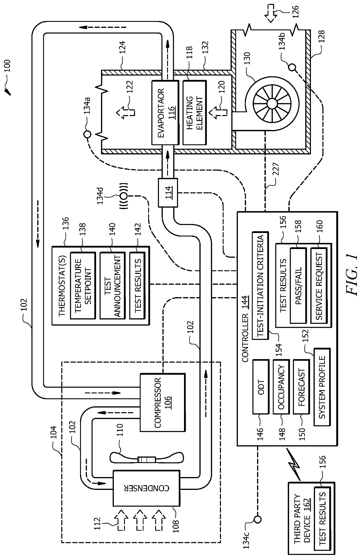
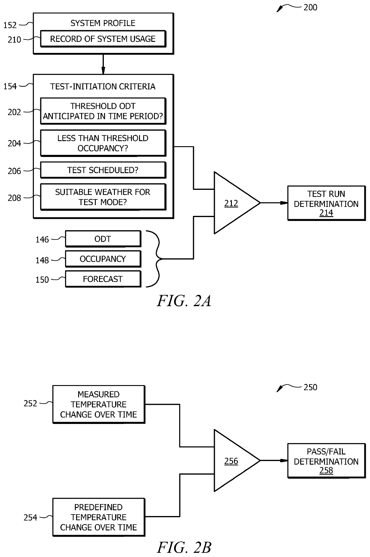
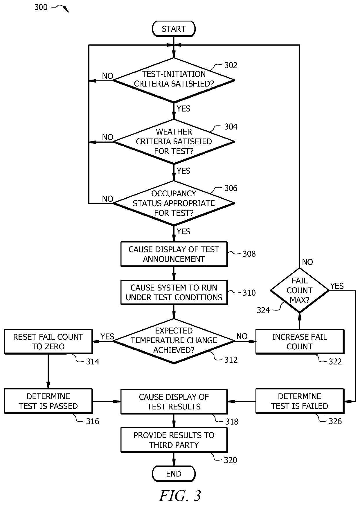
[0043]FIG. 3 is a flowchart illustrating an example method 300 of system prognostics for the HVAC system 100 illustrated in FIG. 1. Method 300 generally facilitates the detection of system faults associated with an operating mode that is anticipated to be needed in the relatively near future for the HVAC system 100. For instance, method 300 facilitates testing of heating mode when the HVAC system is currently operated in a cooling mode (and vice versa). The method 300 may begin at step 302 where the controller 144 determines whether test-initiation criteria 154 are satisfied for the HVAC system 100. The test-initiation criteria 154 generally correspond to an anticipated future need for operation of the HVAC system 100 in an alternative mode (e.g., a cooling mode if the system 100 is currently operated in the heating mode, and vice versa) within a predefined time interval (e.g., about three weeks or so). For instance, for testing cooling mode operation, the test-criteria ...

example controller

[0054]FIG. 4 is a schematic diagram of an embodiment of the controller 144. The controller 144 includes a processor 402, a memory 404, and an input / output (I / O) interface 406.

[0055]The processor 402 includes one or more processors operably coupled to the memory 404. The processor 402 is any electronic circuitry including, but not limited to, state machines, one or more central processing unit (CPU) chips, logic units, cores (e.g. a multi-core processor), field-programmable gate array (FPGAs), application specific integrated circuits (ASICs), or digital signal processors (DSPs) that communicatively couples to memory 404 and controls the operation of HVAC system 100. The processor 402 may be a programmable logic device, a microcontroller, a microprocessor, or any suitable combination of the preceding. The processor 402 is communicatively coupled to and in signal communication with the memory 404. The one or more processors are configured to process data and may be implemented in hardw...


PUM


Abstract

An HVAC system includes a controller configured to receive weather forecast information including anticipated future outdoor temperatures. Based at least in part on the weather forecast information, the controller determines that test-initiation criteria are satisfied for testing operation of the HVAC system in a test mode. In response to determining that the test-initiation criteria are satisfied, the controller determines that current weather conditions are suitable for operating the HVAC system in the test mode for a test time period. The HVAC system is operated in the test mode for the test time period. Following operation of the HVAC system in the test mode for the test time period, the controller determines whether a predefined change in an indoor air temperature is achieved. If the predefined change in the indoor air temperature is achieved, the test is passed. Otherwise, the test is failed.

Description

TECHNICAL FIELD[0001]The present disclosure relates generally to heating, ventilation, and air conditioning (HVAC) systems and methods of their use. In particular, the present disclosure relates to HVAC system prognostics.BACKGROUND[0002]Heating, ventilation, and air conditioning (HVAC) systems are used to regulate environmental conditions within an enclosed space. Air is cooled via heat transfer with refrigerant flowing through the HVAC system and returned to the enclosed space as cooled conditioned air. Air may be heated by a heating element and returned to the enclosed as heated conditioned air.SUMMARY OF THE DISCLOSURE[0003]In an embodiment, a heating, ventilation, and air conditioning (HVAC) system includes a controller configured to receive weather forecast information including anticipated future outdoor temperatures. Based at least in part on the weather forecast information, the controller determines that test-initiation criteria are satisfied for testing operation of the H...

Claims


Application Information

Patent Timeline
Patent Type & Authority Patents(United States)
IPC IPC(8): F24F11/80F24F11/52F24F11/64F24F11/38F24F11/67F24F110/12F24F130/10F24F120/10
CPCF24F11/80F24F11/38F24F11/52F24F11/64F24F11/67F24F2110/12F24F2120/10F24F2130/10F24F11/49F24F2221/54F24F2120/20
Inventor DELGOSHAEI, PAYAMKOWALD, GLENN WILLIAM
Owner LENNOX IND INC
Why Eureka
Try Eureka