Tooling for holding thin metal parts making up a hollow structure in order to enable them to be friction-welded together

a hollow structure and thin metal technology, applied in the field of holder tooling, to achieve the effect of constant quality, robust and reliable, and easy and quick performan

Inactive Publication Date: 2015-11-19
EUROCOPTER
View PDF11 Cites 2 Cited by
  • Summary
  • Abstract
  • Description
  • Claims
  • Application Information

AI Technical Summary

Benefits of technology

[0017]The present invention seeks more particularly to provide such tooling that enables the axial forces to be taken up that result from pressing the welding pin against the edges of the parts, and that also serves to take up the lateral forces that result from tensions induced in the parts during the welding operation so as to avoid deforming the profiles of the resulting hollow structure.
[0019]The present invention also seeks more particularly to provide such tooling that is suitable for holding in shape preformed parts while the welding operation is being performed in order to guarantee that the hollow structure that is obtained has the desired shape. The tooling must also make it possible to accommodate the docking and thickness tolerances of the parts over their entire length, without that affecting the quality of the resulting bead of welding.
[0020]The present invention also seeks more particularly to provide such tooling in which the operations needed to implement it during the various successive steps of welding the parts together are few in number and easy and quick to perform.
[0021]Broadly, the present invention consists in deciding to use the technique of holding parts for a friction welding operation that consists in clamping the parts for welding together between shape-holder members and at least one anvil. The choice of this holding technique seeks to assemble the parts together in a manner that is robust and reliable in spite of their small thickness, of the order of less than 1.5 mm, via a welded joint that is of constant quality along the welded-together parts because of the reliable control achieved over the heat generated and because continuous and stable dynamic recrystallization is obtained of the bead of welding that is being made.
[0029]In particular, the lateral grip member is mounted on the framework via movement means enabling it to move between a disengaged position in which its grip on the preformed parts associated therewith is capable of being interrupted, and a clamping position in which it is suitable for exerting grip on the outer side of said preformed part.
[0032]Preferably, the individual lateral grip members are individually mounted to move on the framework. This subdivision of the lateral grip member enables the clamping positions of individual lateral grip members to be adjusted individually, with the advantage of being able to accommodate tolerances in the straightness of the edges of the preformed parts, and possibly also variations in the thrust they receive in overlap against the section.

Problems solved by technology

These difficulties lie in particular in providing tooling that is as compact as possible and that is suitable for use in forming such hollow structures.

Method used


Image

  • Tooling for holding thin metal parts making up a hollow structure in order to enable them to be friction-welded together
  • Tooling for holding thin metal parts making up a hollow structure in order to enable them to be friction-welded together
  • Tooling for holding thin metal parts making up a hollow structure in order to enable them to be friction-welded together

Examples


Embodiment Construction

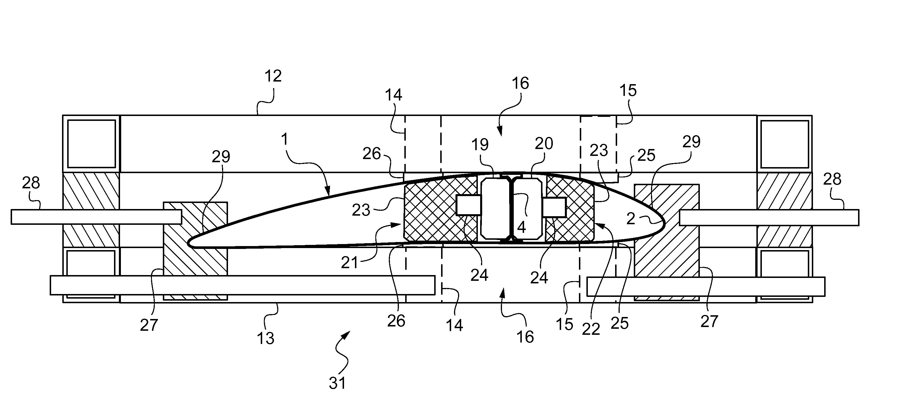
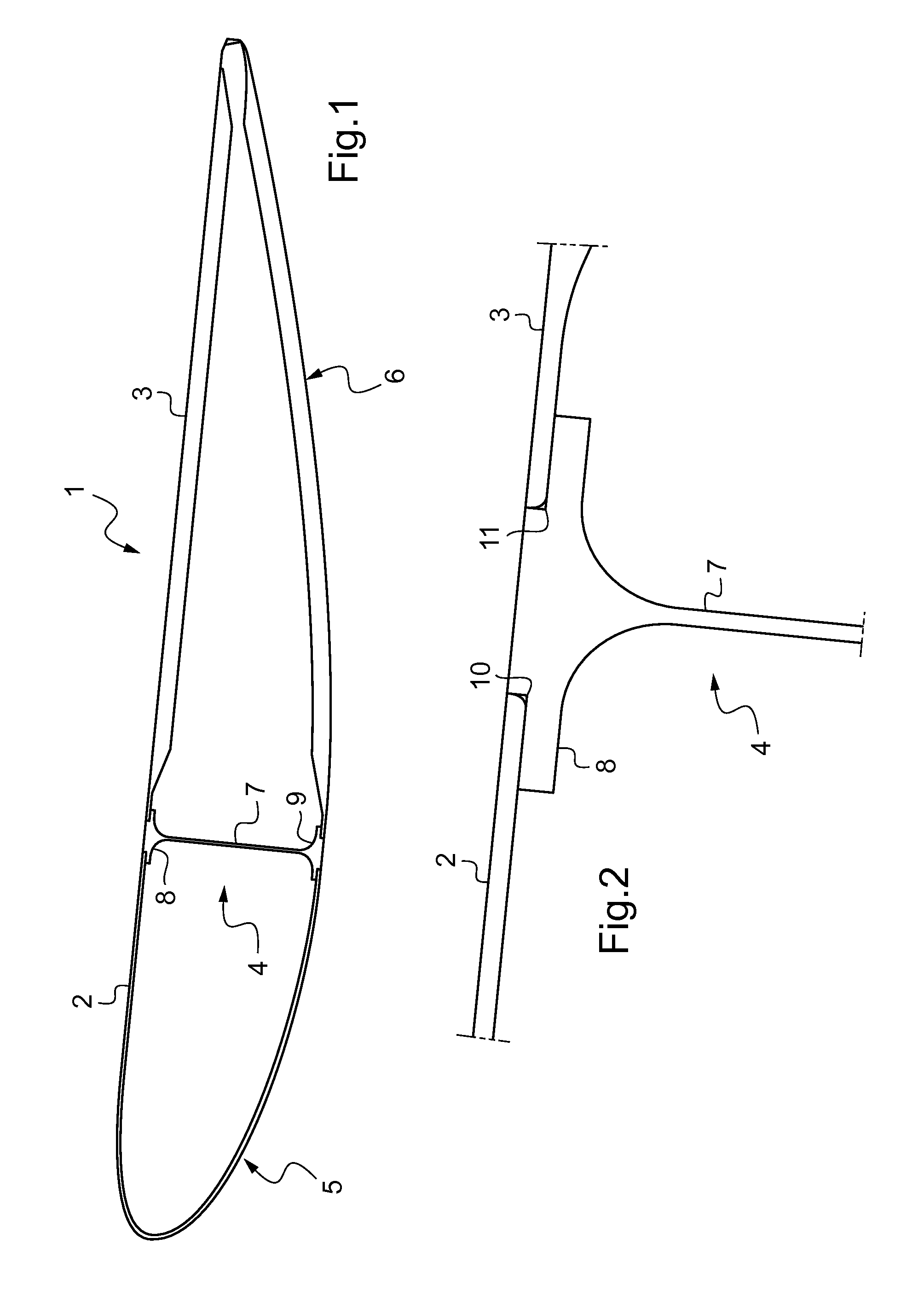
[0050]In FIG. 1, a hollow structure i is obtained from a plurality of parts 2, 3, 4 that are welded to one another by friction. In the embodiment shown, the hollow structure 1 is an airfoil that presents a leading profile and a trailing profile 6, and that includes an internal stiffening section 4. This hollow structure 1 has an overall height of about 70 mm for a width of about 500 mm and a length in its general extension plane of about 3000 mm. Two parts 2 and 3 are preshaped respectively to form the leading profile 5 and the trailing profile 6, and they are assembled together via the section 4. With reference also to FIG. 2, the section 4 is an I-shaped member made up of a web 7 provided at each of its ends with a flange 8, 9 that is used for welding the section 4 to the corresponding edges of the preformed parts 2, 3. Each of the flanges 8, 9 of the section 4 has rabbets i0, ii for receiving in overlap the corresponding edges of the preformed parts 2, 3 using the “self-holding j...


PUM

PropertyMeasurementUnit
thicknessaaaaaaaaaa
thicknessaaaaaaaaaa
lengthaaaaaaaaaa

Abstract

A tooling for holding a set of preformed parts to be friction-welded together to construct a generally plane hollow structure is provide. The tooling includes a framework for receiving the preformed parts inside the framework for welding together to form the hollow structure. The framework includes shape-holder members which are shaped to correspond and contact the outer surfaces of the preformed parts. At least one anvil is disposed inside the framework. A reversible clamp is installed inside the framework and movable into a clamping position in which the clamp inflates to apply opposing thrust in at least two directions such that thrust is applied in a lateral direction to the anvil and applied in a second direction to the inside surface of the preformed parts disposed. The set of preformed parts is held in a welding position with the clamp and framework while a welding operation is performed.

Description

CROSS-REFERENCE TO RELATED APPLICATIONS[0001]This application is a division of U.S. application Ser. No. 12 / 724,455 filed Mar. 16, 2010, which, in turn, claims priority of French Application Serial No. FR 0902023 filed Apr. 27, 2009, the disclosures of which are hereby incorporated in their entirety by reference herein.TECHNICAL FIELD[0002]The invention lies in the technical field of using friction-welding to weld together various thin metal parts for assembly. The invention provides holder tooling for holding said parts to enable them to be friction-welded together, so as to obtain a hollow structure such as an airfoil, a tail fin, or an analogous hollow structure.BACKGROUND[0003]Welding techniques include those performed by friction, such as so-called “friction stir welding” (FSW). Such a technique is advantageous for assembling together metal parts that are thin, e.g. presenting thickness of less than about 1.5 millimeters (mm). By way of example, such parts are constituted by pl...

Claims


Application Information

Patent Timeline
Patent Type & Authority Applications(United States)
IPC IPC(8): B23K20/12B23K37/04
CPCB23K20/126Y10T29/50B23K37/0435B23K37/0443B23P2700/01B64C3/26B64F5/10B23K2101/045Y10T29/49998B23K20/122
Inventor ALLEHAUX, DELPHINEGATTI, JEAN-LOUPMARCHIONE, LAURENTDURAND
Owner EUROCOPTER
Why Eureka
Try Eureka