Electric charging center with fast-charging stations

a charging center and electric vehicle technology, applied in the direction of electric vehicles, battery/fuel cell control arrangements, battery/cell collapse, etc., can solve the problems of power supply collapse, power grid overload in electric vehicle charging facilities according to the state of the art, power supply interruption of electric vehicle charging facilities

Inactive Publication Date: 2015-11-19
ENRICHMENT TECH CO LTD
View PDF5 Cites 41 Cited by
  • Summary
  • Abstract
  • Description
  • Claims
  • Application Information

AI Technical Summary

Benefits of technology

[0007]It is the objective of the present invention to put forward a reliable electric-vehicle charging facility that is suitable for the parallel fast charging of several mobile storage devices.

Problems solved by technology

If the electric-vehicle charging facility is supplied only from the general power grid, this would lead to overloading of the general power grid, which, under certain circumstances, might even cause a collapse of the power supply.
Even with the operation of just a single fast-charging station, in the case of a full output of the fast-charging station and a weak general power grid, it is possible that the general power grid in an electric-vehicle charging facility according to the state of the art might become overloaded.
If it is a main service fuse, it would be triggered in case of an overload, thereby interrupting the power supply of the electric-vehicle charging facility.
The more fast-charging stations are available at an electric-vehicle charging facility, the more often such an overload state can occur in electric-vehicle charging facilities that do not have additional extra energy-storage devices, especially in view of the rising number of electric vehicles that can be expected in the future.

Method used


Image

  • Electric charging center with fast-charging stations
  • Electric charging center with fast-charging stations
  • Electric charging center with fast-charging stations

Examples


Embodiment Construction

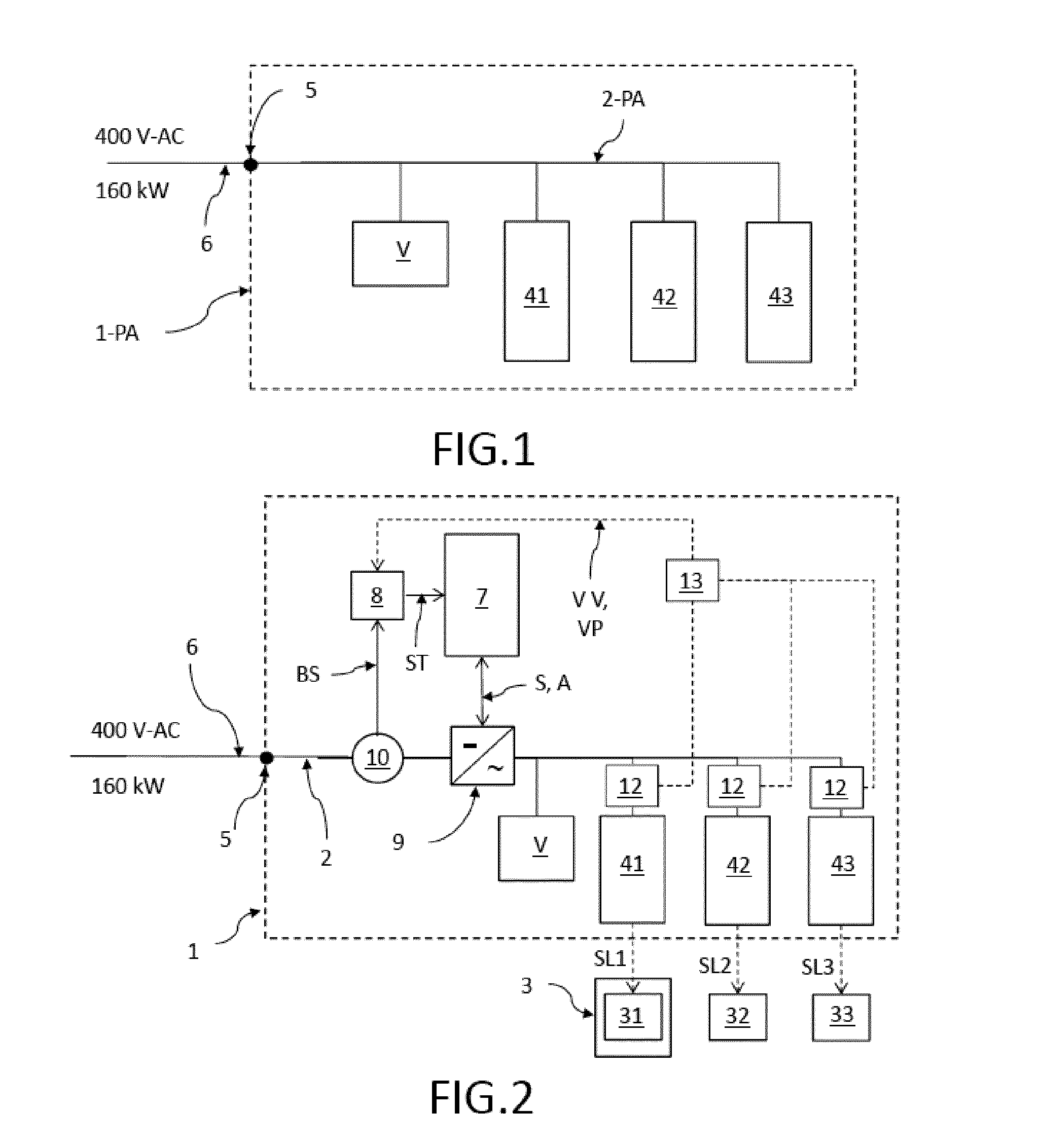
[0040]FIG. 1 shows an electric-vehicle charging facility 1-PA according to the state of the art, whereby the electric-vehicle charging facility 1-PA has an AC power supply system 2-PA that is connected at a transfer point 5 (for example, a main service fuse) to the general power grid 6 with 400 V-AC and 160 kW. The electric-vehicle charging facility 1-PA according to the state of the art can have one or more charging stations 41, 42, 43 that can optionally also be configured as fast-charging stations. Due to the limitations associated with the general power grid 6, the charging stations 41, 42, 43 cannot be used in parallel and / or only with a limited charging output whenever there is a high charging demand. Particularly when there is a large number of electric vehicles to be charged at the electric-vehicle charging facility 1-PA, this results in long waiting times for the charging and thus in long waiting times for the electric vehicles, which would greatly restrict the times when s...


PUM


Abstract

An electric-vehicle charging facility is disclosed having at least one load-cycling-resistant energy-storage device. The electric-vehicle charging facility comprises at least one fast-charging station, hooked up to the AC power supply system that is connected via a transfer point to the general power grid, and comprises at least one load-cycling-resistant energy-storage device having an energy-storage device control unit, whereby the load-cycling-resistant energy-storage device is connected via an AC / DC transformer to the AC power supply system the electric-vehicle charging facility in order to store energy drawn from the general power grid and in order to deliver electric energy to the AC power supply system of the electric-vehicle charging facility response to the demand.

Description

FIELD OF THE INVENTION[0001]The invention relates to an electric-vehicle charging facility having at least one load-cycling-resistant energy-storage device, suitable for the parallel fast charging of several mobile storage devices, it also relates to a method for the operation of such an electric-vehicle charging facility, and to a method for retrofitting a conventional electric-vehicle charging facility in order to create the electric-vehicle charging facility according to the invention.BACKGROUND OF THE INVENTION[0002]An electric vehicle with an electric drive is superior to a conventional vehicle with an internal combustion engine in many aspects. These include, for example, the much higher efficiency as well as the advantageous torque and performance characteristics of the electric motor, the usually simpler construction of the drive train, and the fact that it is almost completely emission-free in terms of pollutants and noise on the local level. Electric cars are thus very wel...

Claims


Application Information

Patent Timeline
Patent Type & Authority Applications(United States)
IPC IPC(8): B60L11/18
CPCB60L11/185B60L11/1803B60L11/1851B60L11/1824H02J1/102Y02T90/14Y04S10/126B60L50/51B60L53/30B60L55/00B60L53/63B60L53/11B60L58/10B60L53/56B60L53/53H02J7/342Y02E60/00Y02T10/70Y02T10/7072Y02T90/12H02J7/0013H02J7/0029H02J2310/48H02J7/00306
Inventor DUREAU, GUILLAUMEVOR DEM ESCHE, RAINERTREPPMANN, CHRISTOPH
Owner ENRICHMENT TECH CO LTD
Why Eureka
Try Eureka