A Railway Sleeper

a railway and sleeper technology, applied in the field of railway sleepers, can solve the problems of increasing the cost of railway sleepers, reducing the long-held advantages of high-quality hardwoods, and reducing the supply of high-quality hardwoods,

Inactive Publication Date: 2015-11-19
CARBONLOC
View PDF1 Cites 13 Cited by
  • Summary
  • Abstract
  • Description
  • Claims
  • Application Information

AI Technical Summary

Benefits of technology

[0010]It is an object of the invention to overcome or alleviate one or more of the above disadvantages or provide the consumer with a useful or commercial choice. It is the preferred object of this invention to enable railway sleepers to be produced with a similar depth / size as hardwood timber sleepers.
[0013]It is a still further preferred object of the invention to allow railway sleepers to be produced cost effectively.
[0014]It is a still further preferred object of the invention to allow railway sleepers to be produced that have excellent durability and are able to resist biological and chemical attack.

Problems solved by technology

Timber railway sleepers generally perform well, but changes in environmental awareness and rapidly diminishing supplies of high quality hardwoods have reduced their long held advantages.
Further, the cost of timber railway sleepers is increasing year on year.
With millions of timber railway sleepers requiring replacement each year in existing railway lines, there has been difficulty in finding suitable replacement railway sleepers from alternative materials.
Concrete railway sleepers have gained increasing acceptance, but their stiffness typically limits their use to locations where complete sleeper replacement is undertaken or where new track is constructed.
Due to their increased depth (approximately 280 mm compared to 120 mm for hardwood timber) concrete sleepers cannot be readily used to replace single sleepers.
Further, this increased depth of the concrete railway sleepers also requires significantly more ballast than timber railway sleepers.
Also concrete sleepers have a much higher stiffness than timber railway sleepers, making them unsuitable to replace timber railway sleepers in many applications where some compliance is desired.
The high weight of concrete sleepers (about three to four times that of timber sleepers) makes them expensive to transport and difficult to handle with conventional timber railway sleeper replacement technology.
Steel railway sleepers can be interspersed with timber sleepers but they are generally too light, have poor bearing characteristics, and require high maintenance.
A further difficulty with using steel or concrete to produce replacement timber railway sleepers is that the current fastening systems used for timber cannot be utilised.

Method used


Image

  • A Railway Sleeper
  • A Railway Sleeper
  • A Railway Sleeper

Examples


Embodiment Construction

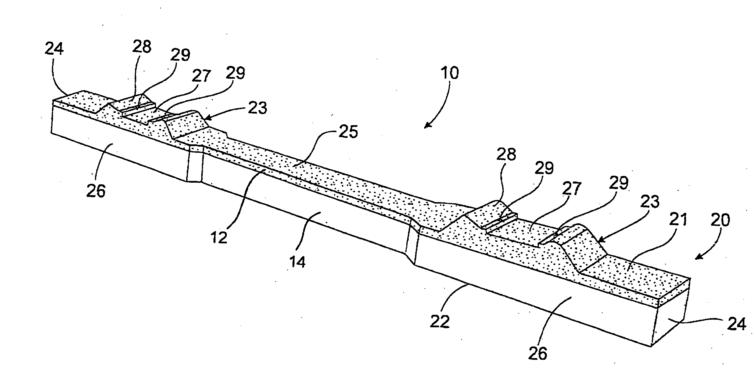
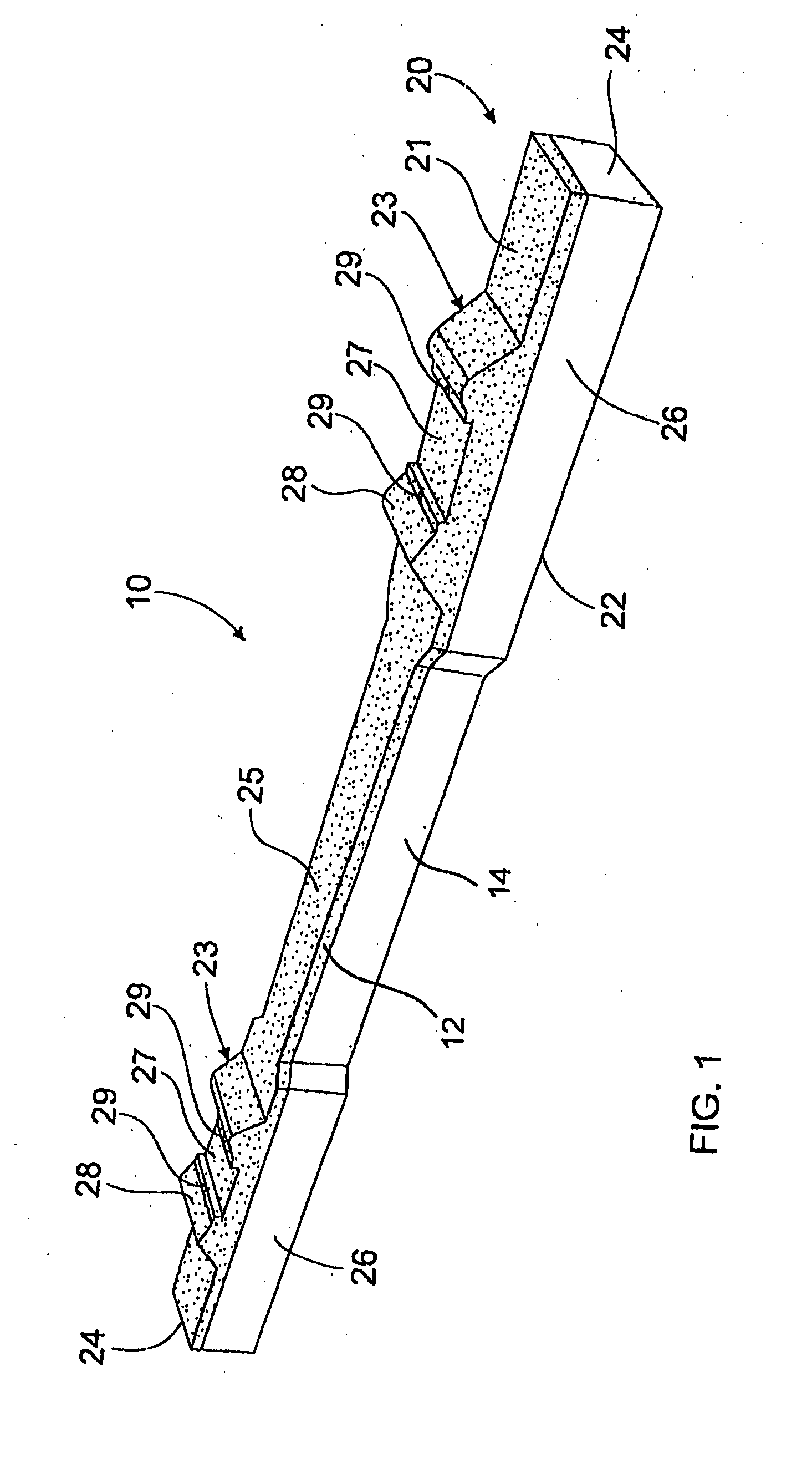
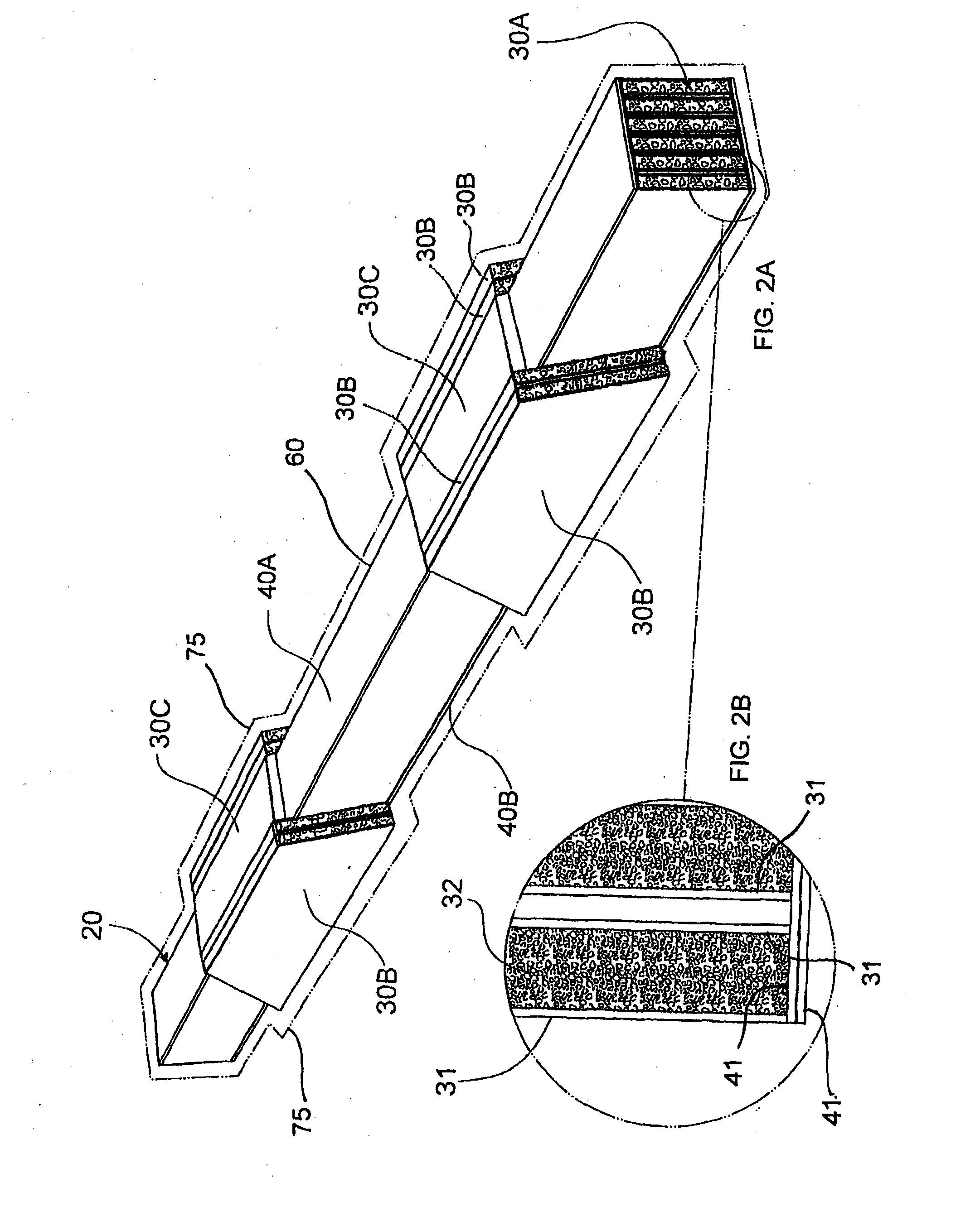
[0064]FIGS. 1 and 2 show a railway sleeper 10 that can be used for replacement of a timber sleeper. The sleeper 10 is constructed from a body 20, a series of sandwich panels 30 and two sheet-like fibre composite members 40A and 40B.

[0065]The body 20 is constructed from polymer concrete into which is embedded reinforcements. The body has a top face 21 for placement of a railway rail and a bottom face 22 which in use of the railway sleeper. 10 bears onto a bed of ballast, typically coarse graded rock. The railway sleeper 10 has two rail seats 23, two ends 24 and a middle section 25. A pair of wings 26 extend sideways from the body 20 adjacent each rail seat 23. Each rail seat 23 has a recess 27 with two raised portions 28 extending away from the recess 27. A fastening hole 29 is located adjacent each of the raised portions for engagement with a fastener.

[0066]The polymer concrete which forms an upper part of the body 20 is formed with approximately 28% by volume of epoxy resin includi...


PUM

PropertyMeasurementUnit
depthaaaaaaaaaa
sizeaaaaaaaaaa
specific gravityaaaaaaaaaa

Abstract

A railway sleeper comprising a body having a top face on which railway rails are located and a bottom face for placement on a ground surface. The body is formed from a plurality of fibre composite sandwich panels plus a polymer concrete comprising an amount of polymer resin and an amount of filler. Each sandwich panel has a pair of fibre composite skins with a structural core material located therebetween. The fibre composite sandwich panels extend longitudinally within said body.

Description

FIELD OF THE INVENTION[0001]This invention relates to a railway sleeper. In particular the invention relates to a railway sleeper which may be used as a replacement railway sleeper for timber railway sleepers and therefore will be described in this context. However, it should be appreciated that the railway sleeper may be used for other applications.[0002]Railway sleepers are called ties in some countries so use of the term sleeper in this specification also refers to tie.BACKGROUND OF THE INVENTION[0003]Worldwide, the railway industry installs millions of railway sleepers each year. A significant number of these sleepers are used to maintain existing lines while the rest are used to construct new railway lines. The materials traditionally utilised for new railway sleepers are timber, concrete or steel.[0004]Timber railway sleepers generally perform well, but changes in environmental awareness and rapidly diminishing supplies of high quality hardwoods have reduced their long held ad...

Claims


Application Information

Patent Timeline
Patent Type & Authority Applications(United States)
IPC IPC(8): E01B3/36B29C39/10
CPCE01B3/36B29K2103/08B29K2309/06B29C39/10B29D99/0003B32B27/065B32B27/20B32B1/00B32B3/10B32B2250/40B32B2262/0269B32B2262/101B32B2262/106B32B2307/714E01B3/46
Inventor VAN ERP, GERARDUS MARIA
Owner CARBONLOC
Why Eureka
Try Eureka