Velocity interferometer for any reflector with variable sensitivity range and time resolution

a technology of velocity interferometer and reflector, which is applied in the field of velocity interferometer system for any reflector, can solve the problems of reducing the accuracy of displacement interferometer, so as to achieve the effect of facilitating generation

Active Publication Date: 2015-11-19
DIRECTOR GENERAL DEFENCE RES & DEV ORG
View PDF1 Cites 9 Cited by
  • Summary
  • Abstract
  • Description
  • Claims
  • Application Information

AI Technical Summary

Benefits of technology

[0022]The present disclosure also provides a velocity interferometer system, a first optical cell including a first optical reflective component; a second optical cell including a second optical reflective component; a beam splitter configured to amplitude split incident light beam, direct the split light beam into said first and second optical cells via a first and second light path respectively, and recombine the reflected beams; at least one wave plate located between beam splitter and one of the optical cells to facilitate generation of two fringe patterns having fringe shift of a quarter wave; at least one polarized beam splitter to separate out two fringe patterns having fringe shift of a quarter wave; at least one pair of detectors for detecting the movem

Problems solved by technology

Recording velocity time history of highspeed projectiles created by shockwaves, high energy plasmas and other rapid-acceleration devices is a major challenge for explosives and shock dynamic research labs, all over the world.
Both these techniques, however, provide only an average velocity of the projectile and offer limited accuracy.
One major difficulty with this approach is that the Doppler shift obtained is, in general, very large, which imposes serious constraints on the bandwidth of detectors and measuring equipment.
Moreover, displacement interferometers put stringent requirements on temporal and s

Method used


Image

  • Velocity interferometer for any reflector with variable sensitivity range and time resolution
  • Velocity interferometer for any reflector with variable sensitivity range and time resolution
  • Velocity interferometer for any reflector with variable sensitivity range and time resolution

Examples


Embodiment Construction

)

[0032]The terms “comprises”, “comprising”, or any other variations thereof, are intended to cover a non-exclusive inclusion, such that a process, method that comprises a list of steps does not include only those steps but may include other steps not expressly listed or inherent to such process, method. Similarly, one or more elements in a system or apparatus proceeded by “comprises . . . a” does not, without more constraints, preclude the existence of other elements or additional elements in the system or apparatus.

Overview

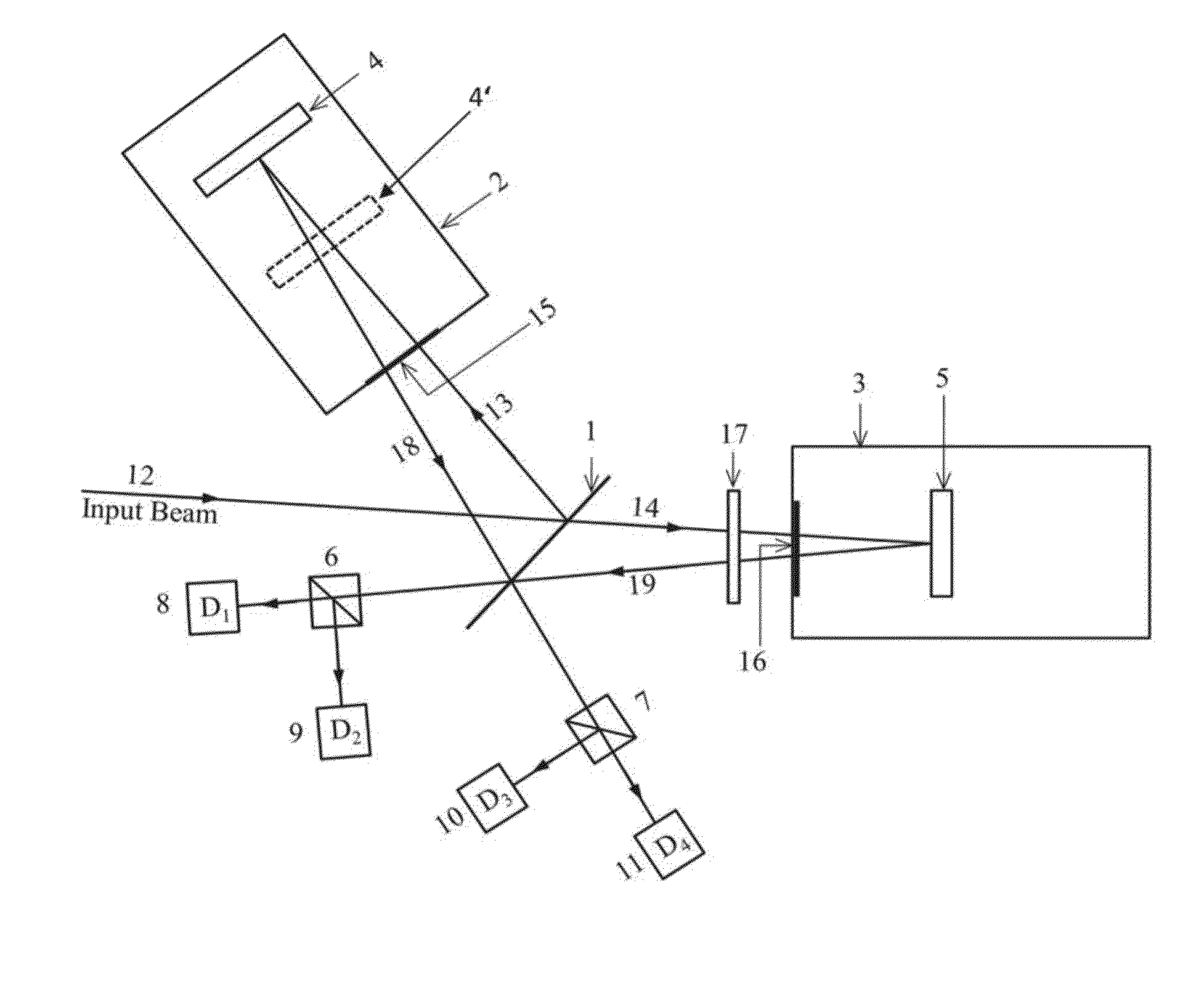
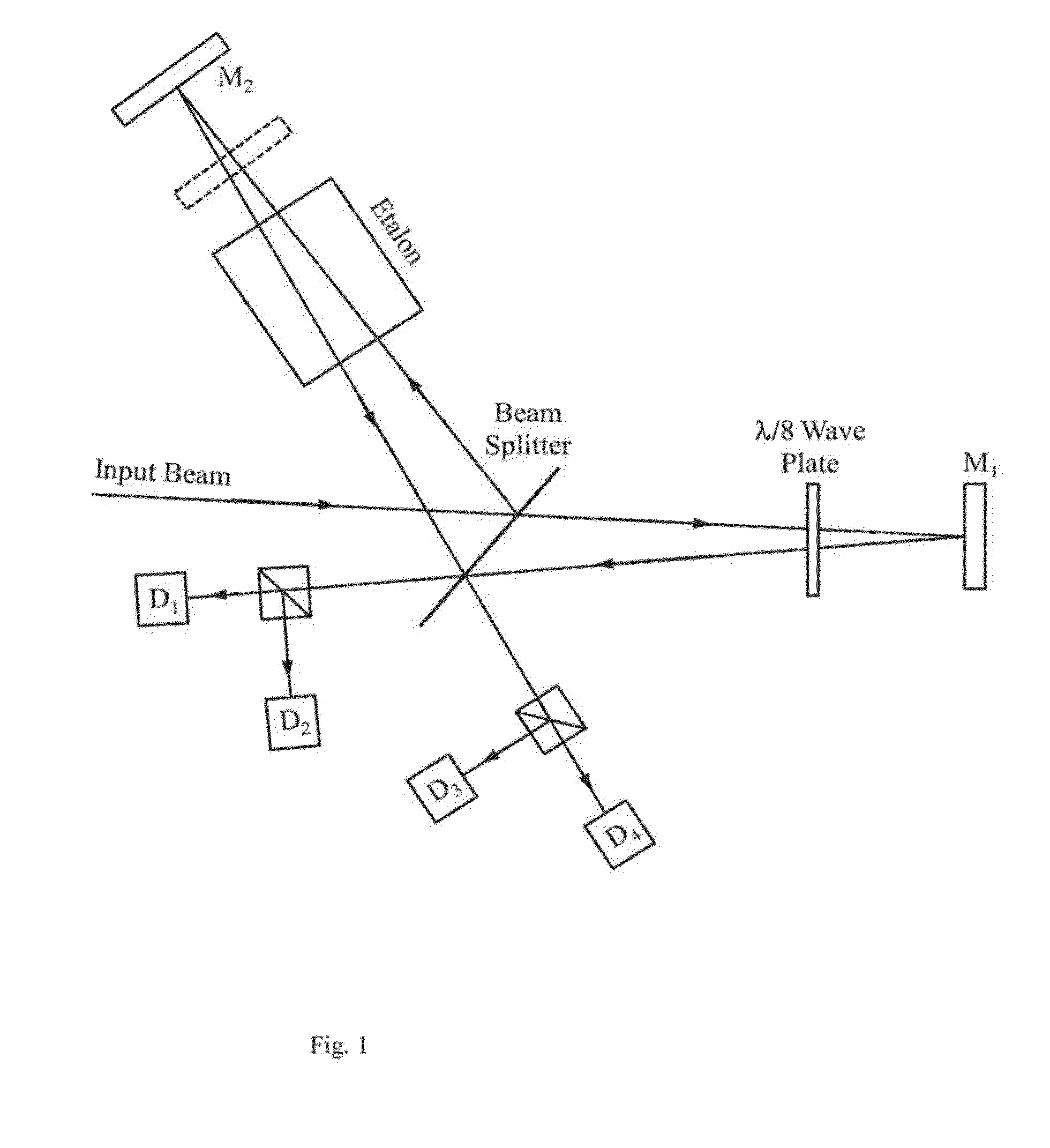
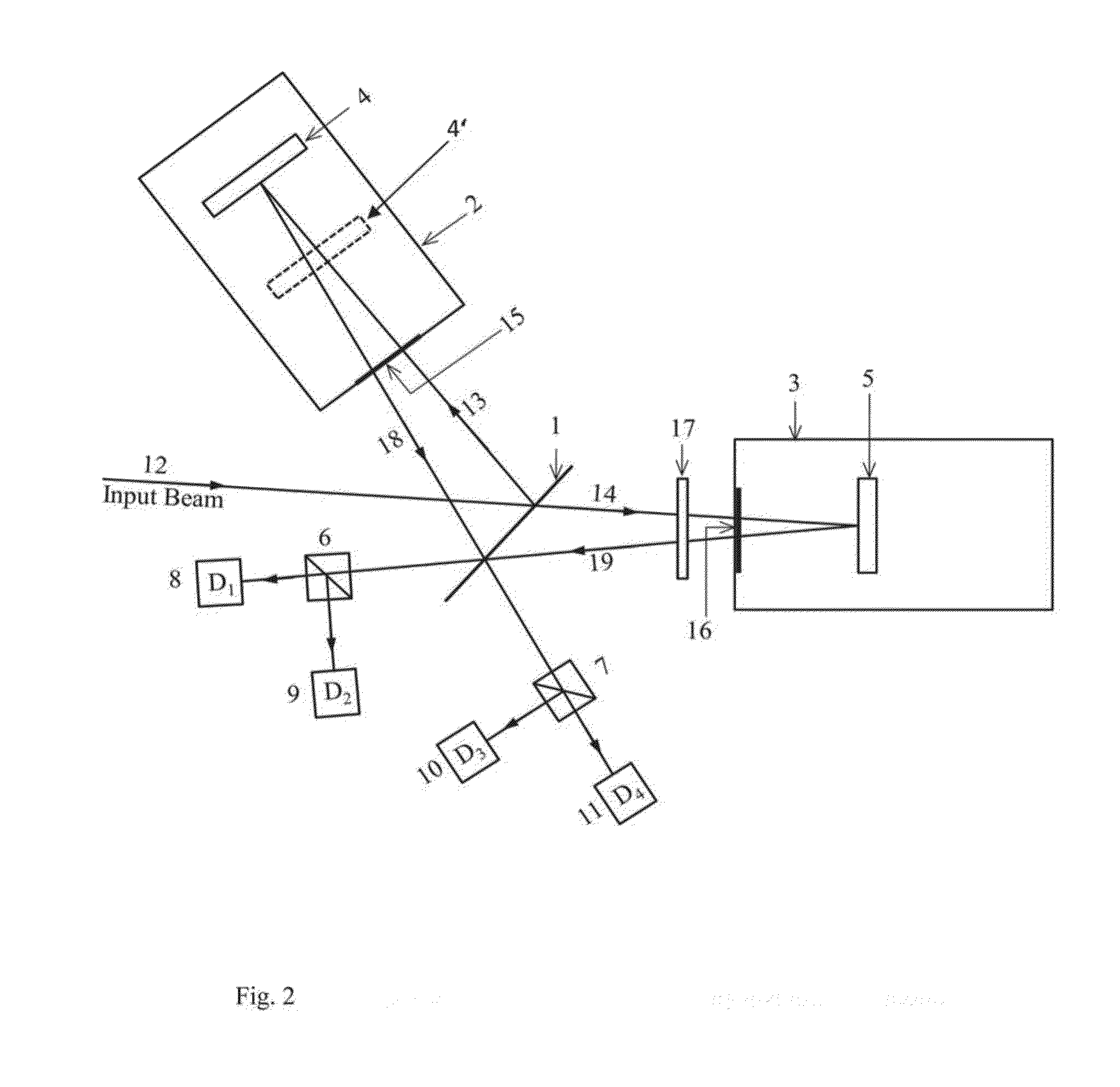
[0033]Accordingly, the present disclosure relates to a velocity interferometer. The interferometer described herein, comprises of two optical cells, one partially containing a liquid. The light entering the interferometer is amplitude split and made to propagate through the two cells in such a way that the optical path lengths of the beams are equal, thereby fulfilling the condition necessary for obtaining single wide fringe in the interference pattern of the two...


PUM


Abstract

The present disclosure relates to a velocity interferometer. The interferometer described herein, comprises of two optical cells, one partially containing a liquid. The light entering the interferometer is amplitude split and made to propagate through the two cells in such a way that the apparent path lengths of the beams are equal, thereby fulfilling the condition necessary for obtaining single wide fringe in the interference pattern of the two beams. However, due to difference in the physical path traversed by the two beams, a finite delay time exists between them. The two beams, after reflection from end-mirrors or cube corner prisms in the two cells are recombined to form interference fringe patterns on active areas of multiple detectors. Doppler shifted light resulting from reflection of light from a moving projectile generate fringe shifts on the detector planes thereby producing voltage signals proportional to instantaneous velocity of fast moving projectile. The voltage signals are recorded with multi-channel digital oscilloscope and processed in a processor/controller of a computing unit to obtain velocity time history of the projectile. Controlled motion of the cube corner reflectors placed at the ends of two cells using stepper motors and piezoelectric actuators ensures that the time delay between the interfering beams is controlled accurately thereby changing the sensitivity range and time resolution of the velocity measurements.

Description

RELATED APPLICATIONS[0001]This application claims the priority benefit of Indian Patent Application No. 1305 / DEL / 2014 filed on May 16, 2014.FIELD[0002]The present disclosure relates to the field of interferometer. Particularly, the present disclosure deals with a velocity interferometer system for any reflector (VISAR).BACKGROUND[0003]Recording velocity time history of highspeed projectiles created by shockwaves, high energy plasmas and other rapid-acceleration devices is a major challenge for explosives and shock dynamic research labs, all over the world. The velocity of such fast moving projectiles ranges typically from 1-100 km / sec and is associated with large acceleration and retardation. The total time for recording velocity time history of such rapid moving surfaces is no more than a few micro seconds putting major constraints on the response time of measurement systems. Important optical techniques for measuring velocity under such extreme conditions, often encountered in dyn...

Claims


Application Information

Patent Timeline
IPC IPC(8): G01P3/36
CPCG01P3/36G01S17/58
Inventor GHAI, DEVINDER PALSWAMI, HET RAMMAINI, ANIL KUMAR
Owner DIRECTOR GENERAL DEFENCE RES & DEV ORG
Why Eureka
Try Eureka