
Sheet for illumination, printed matter for illumination, method of producing printed matter for illumination, and illumination signboard

Inactive Publication Date: 2015-11-19
FUJIFILM CORP
View PDF3 Cites 0 Cited by
  • Summary
  • Abstract
  • Description
  • Claims
  • Application Information

AI Technical Summary

Benefits of technology

The present invention aims to provide a sheet for illumination, a printed matter for illumination, and a method of producing a printed matter for illumination that can suppress the reflection of external light without compromising the sharpness of the printed image. The inventors found that this can be achieved by laminating an easily-adhesive layer, a support, and a mat layer in this order and satisfying a predetermined relationship between a transmission value and an image clarity value. This mechanism helps to improve image clarity while reducing the reflection of external light.

Problems solved by technology

However, in the sheets of PTLs 1 and 2, since the haze thereof is largely increased, reflection of external light is reduced, but sharpness of a printed image is degraded.

Method used


Image

  • Sheet for illumination, printed matter for illumination, method of producing printed matter for illumination, and illumination signboard
  • Sheet for illumination, printed matter for illumination, method of producing printed matter for illumination, and illumination signboard
  • Sheet for illumination, printed matter for illumination, method of producing printed matter for illumination, and illumination signboard

Examples


first embodiment

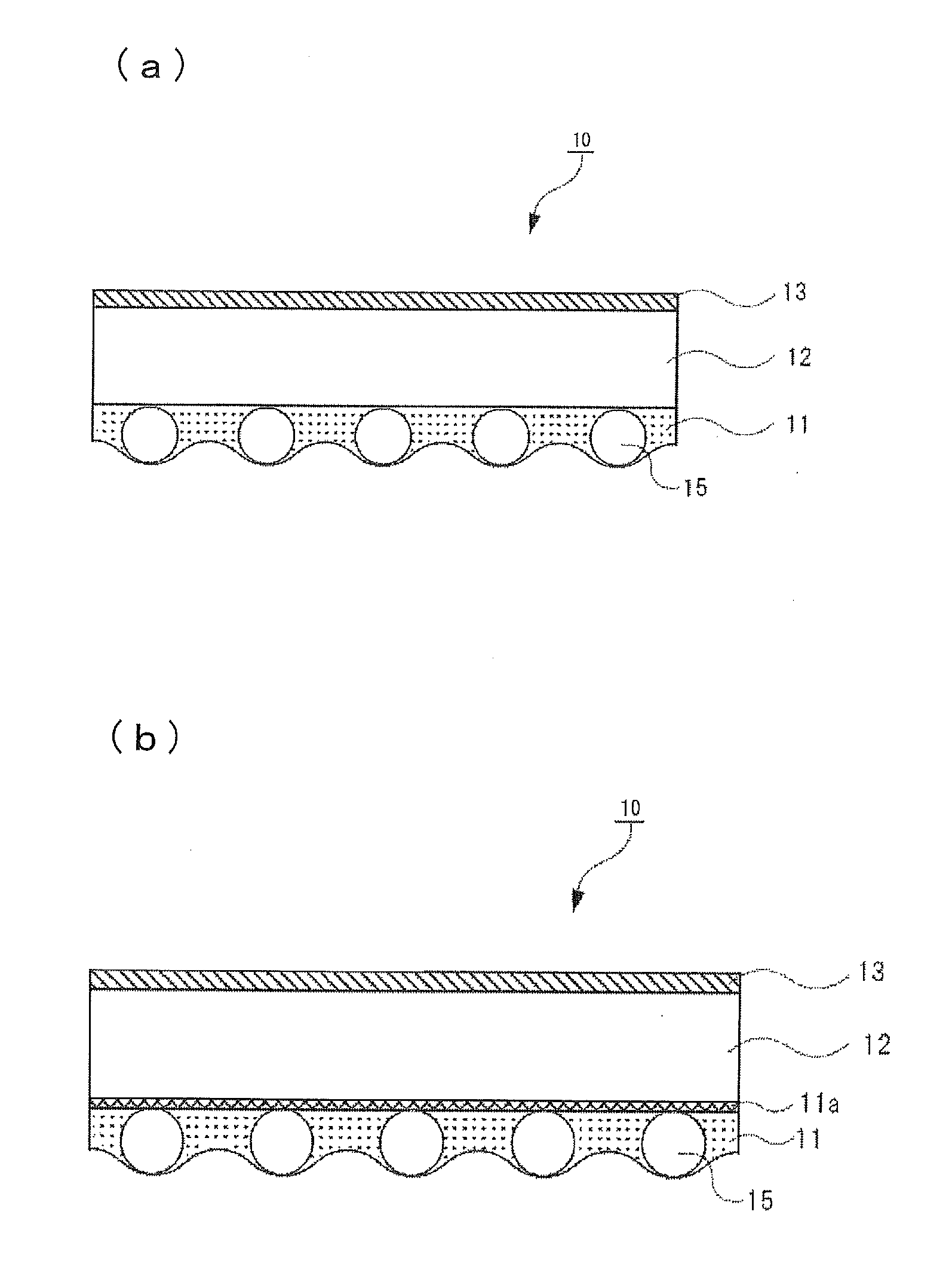
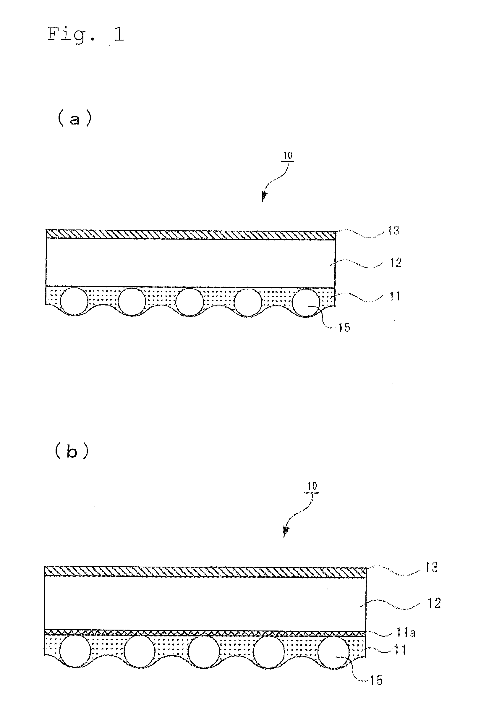
[0048]FIG. 1(a) is a sectional view illustrating an example of a sheet for illumination according to a first embodiment of the present invention. As illustrated in FIG. 1(a), a sheet 10 for illumination of the first embodiment of the present invention is formed by laminating a mat layer 11, a support 12, and an easily-adhesive layer 13, and the surface of the mat layer has certain unevenness. It is preferable that the mat layer 11 is a hard coat layer having hardness and scratch resistance. In this manner, it is possible to prevent the sheet 10 for illumination from being damaged. An image layer is formed by an ink composition being ejected onto the easily-adhesive layer 13. The easily-adhesive layer 13 improves adhesiveness between the support 12 and the image layer.

[0049]The mat layer includes a silicon-containing resin, a matting agent, and a surfactant. The silicon-containing resin contains a condensate obtained by condensing a silane coupling agent. In addition, the silane coup...

second embodiment

[0176]A second embodiment is the same as the first embodiment except that the mat layer contains a matting agent having a particle diameter of 0.4 μm to 3 μm and a binder and a refractive index difference between the matting agent and the binder is 0.1 or less. That is, the support, the intermediate layer, and the easily adhesive layer of the first embodiment can be used for a support, an intermediate layer, and an easily adhesive layer in a sheet for illumination of the second embodiment and the preferable ranges are the same as each other.

[0177]A difference in the refractive index between the matting agent and the binder is preferably 0.1 or less, more preferably 0.08 or less, and still more preferably 0.05 or less. When the difference in the refractive index is in the above-described range, the haze value can be adjusted not to be excessively large. The haze value of the mat layer may be 35% or less, preferably in the range of 3% to 30%, more preferably in the range of 6% to 30%,...

example 1

Preparation of Sheet for Illumination

[0230][Preparation of Support]

[0231]Polyethylene terephthalate (hereinafter, referred to as “PET”) resin in which a Ti compound was polycondensed as a catalyst and whose intrinsic viscosity was 0.66 was dried to have a moisture content of 50 ppm or less and dissolved in an extruder at which a set heater temperature was in the range of 280° C. to 300° C. The dissolved PET resin was ejected onto a chill roll electrostatically applied from a die portion, thereby obtaining an amorphous base. The obtained amorphous base was stretched at a stretch ratio of 3.1 times in the base scanning direction and stretched at a stretch ratio of 3.8 times in the width direction, thereby obtaining a PET support having a thickness of 250 μm.

[0232][Preparation of Easily Adhesive Layer]

[0233]After a corona discharge treatment was performed on a PET support under the condition of 730 J / m2, the corona-treated surface side was coated with a coating liquid A described below...


PUM

PropertyMeasurementUnit
Temperatureaaaaaaaaaa
Lengthaaaaaaaaaa
Fractionaaaaaaaaaa

Abstract

A sheet for illumination including a support, a mat layer which is arranged on one surface of the support, and an easily-adhesive layer which is arranged on the other surface of the support, in which a transmission value in percentage of image clarity in comb teeth with an interval of 2 mm and an image clarity value in percentage of reflection at 60° in comb teeth with an interval of 2 mm when an angle between a traveling direction of light and a normal of a sheet is set to be 60° satisfy (Transmission value in percentage of image clarity) / (image clarity value in percentage of reflection at 60°)≧2, suppresses reflection of external light without degrading sharpness of a printed image.

Description

CROSS-REFERENCE TO RELATED APPLICATIONS[0001]This application is a Continuation of PCT International Application No. PCT / JP2014 / 051818, filed on Jan. 28, 2014, which claims priority under 35 U.S.C. Section 119(a) to Japanese Patent Application No. 2013-014286 filed on Jan. 29, 2013. Each of the above applications is hereby expressly incorporated by reference, in its entirety, into the present application.BACKGROUND OF THE INVENTION[0002]1. Field of the Invention[0003]The present invention relates to a sheet for illumination, a printed matter for illumination, a method of producing a printed matter, and an illumination signboard.[0004]2. Background Art[0005]An ink jet system that ejects an ink composition in a form of droplets from an ink ejection port is small and inexpensive, and used in many printers because of a capability of forming an image in a non-contact manner with respect to a recording medium. Among various ink jet systems, a piezo ink jet system which allows an ink to be...

Claims


Application Information

Patent Timeline
IPC IPC(8): G02B5/02G09F13/00
CPCG02B5/0268G02B5/0294G09F13/00G02B5/02B32B27/06B32B27/20B32B27/283B32B2264/10B32B2307/418B32B2451/00B32B2457/00
Inventor HOSODA, HIDEMASANOMURA, TATSUYASHIMIZU, TAKASHI
Owner FUJIFILM CORP
Learn More