Optical modulator, optical transmitter, optical transmission/reception system, and control method for optical modulator

a control method and optical modulator technology, applied in optics, instruments, electrical equipment, etc., can solve the problem that the voltage distribution of the electrode serving as the means of applying an electric field to the optical phase modulator is no longer regarded as uniform in the optical signal propagation axis direction, and achieve the effect of reducing the power consumption of the optical transmitter

Inactive Publication Date: 2015-11-19
NEC CORP
View PDF2 Cites 11 Cited by
  • Summary
  • Abstract
  • Description
  • Claims
  • Application Information

AI Technical Summary

Benefits of technology

[0014]According to the present invention, it is possible to decrease power consumption of an optical transmitter including a segmented electrode structure.

Problems solved by technology

Therefore, voltage distribution of the electrode serving as means for applying an electric field to the optical phase modulator is no longer regarded as uniform in an optical signal propagation axis direction.

Method used


Image

  • Optical modulator, optical transmitter, optical transmission/reception system, and control method for optical modulator
  • Optical modulator, optical transmitter, optical transmission/reception system, and control method for optical modulator
  • Optical modulator, optical transmitter, optical transmission/reception system, and control method for optical modulator

Examples


first embodiment

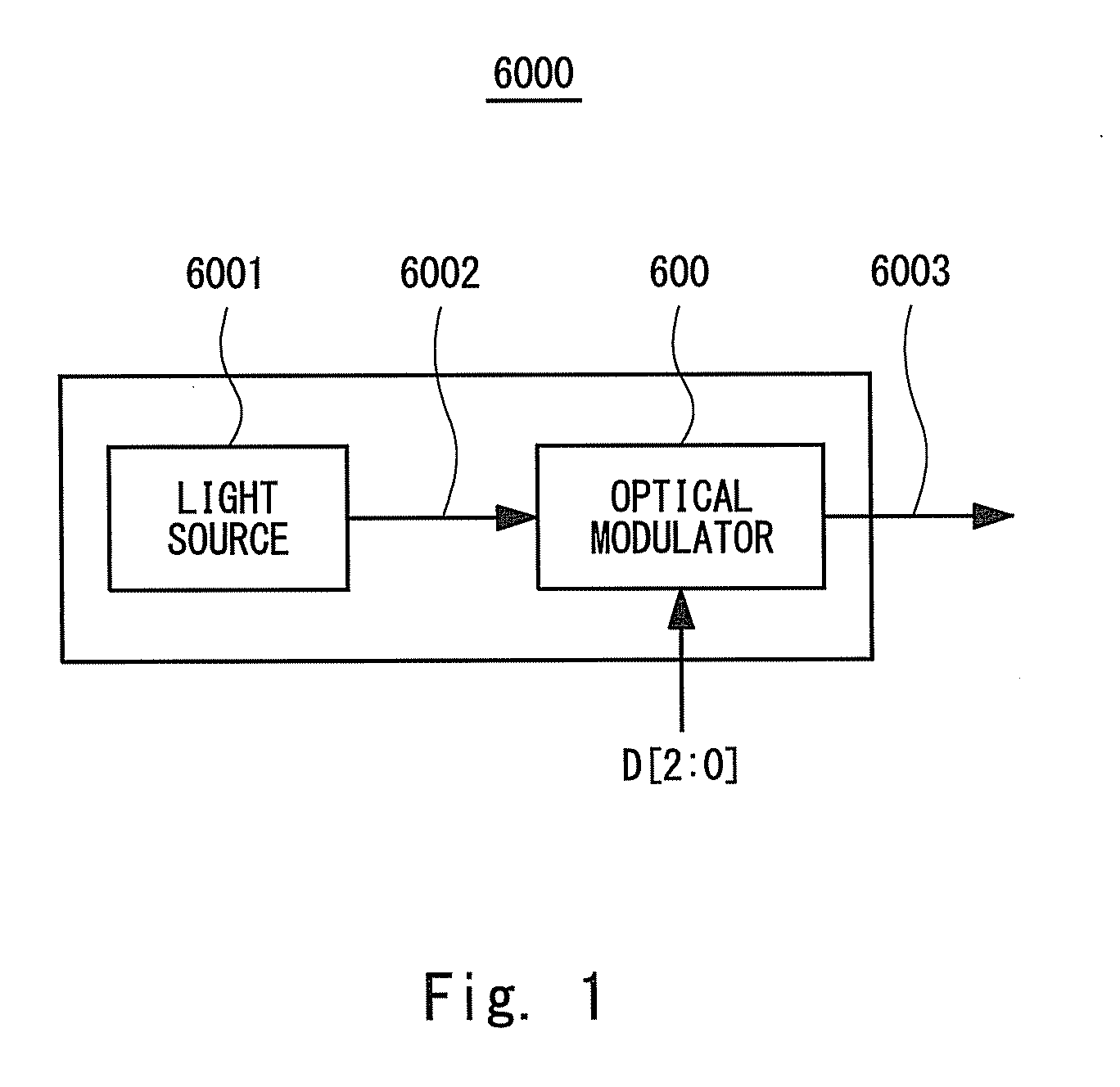
[0063]An optical transmitter 1000 according to a first embodiment of the present invention shall be described. The optical transmitter 1000 is an optical transmitter that preforms a binary (i.e., 1-bit) modulation operation. FIG. 7 is a block diagram schematically showing a configuration of the optical transmitter 1000 according to the first embodiment. The optical transmitter 1000 includes a light source 1001 and an optical modulator 100.

[0064]The light source 1001, which typically consists of a laser diode, outputs CW (Continuous Wave) light 1002 to the optical modulator 100, for example. The optical modulator 100 is a binary (1-bit) optical modulator. The optical modulator 100 modulates the input CW light 1002 to output a binary optical signal 1003 according to an input digital signal DIN that is a binary digital signal.

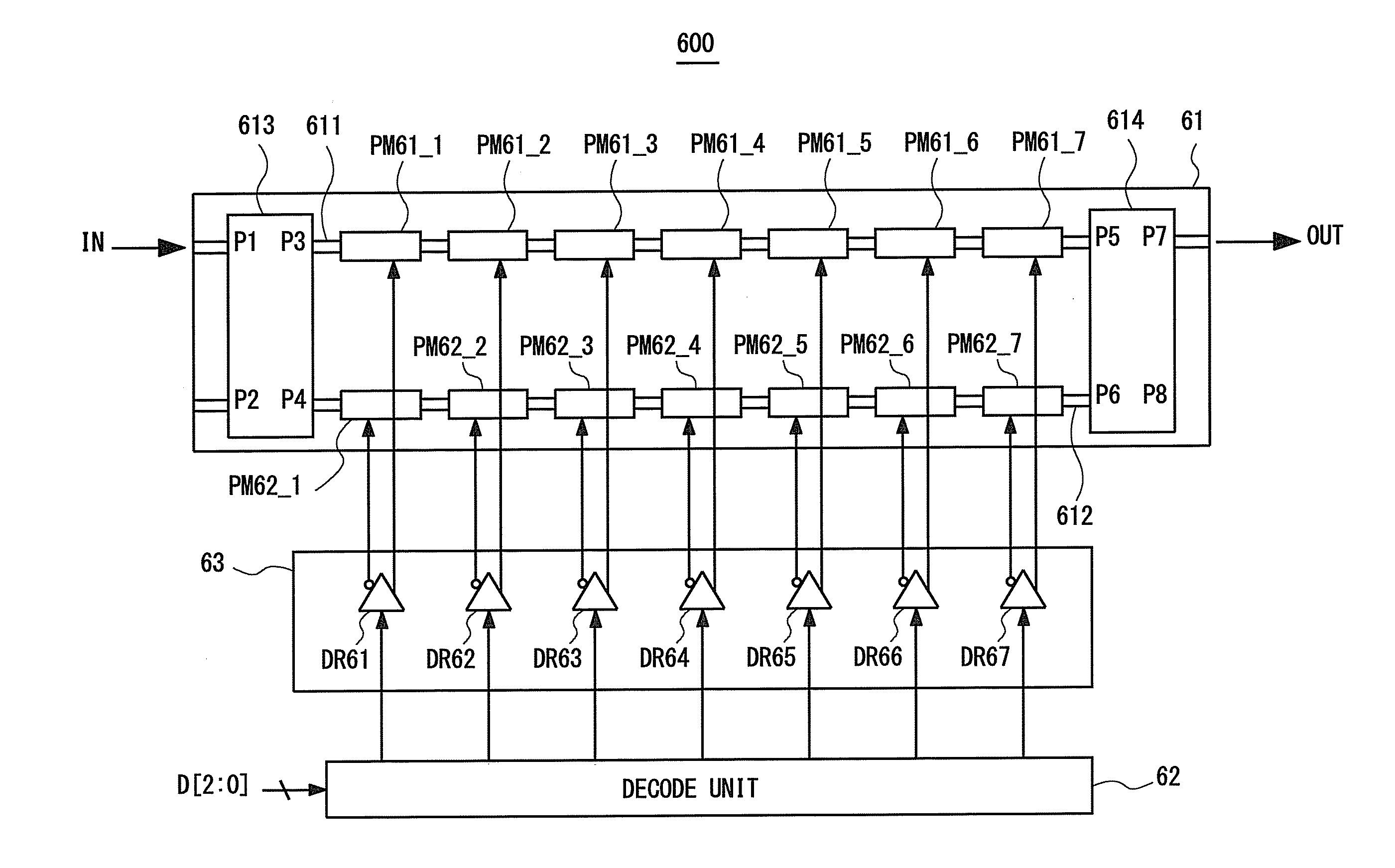
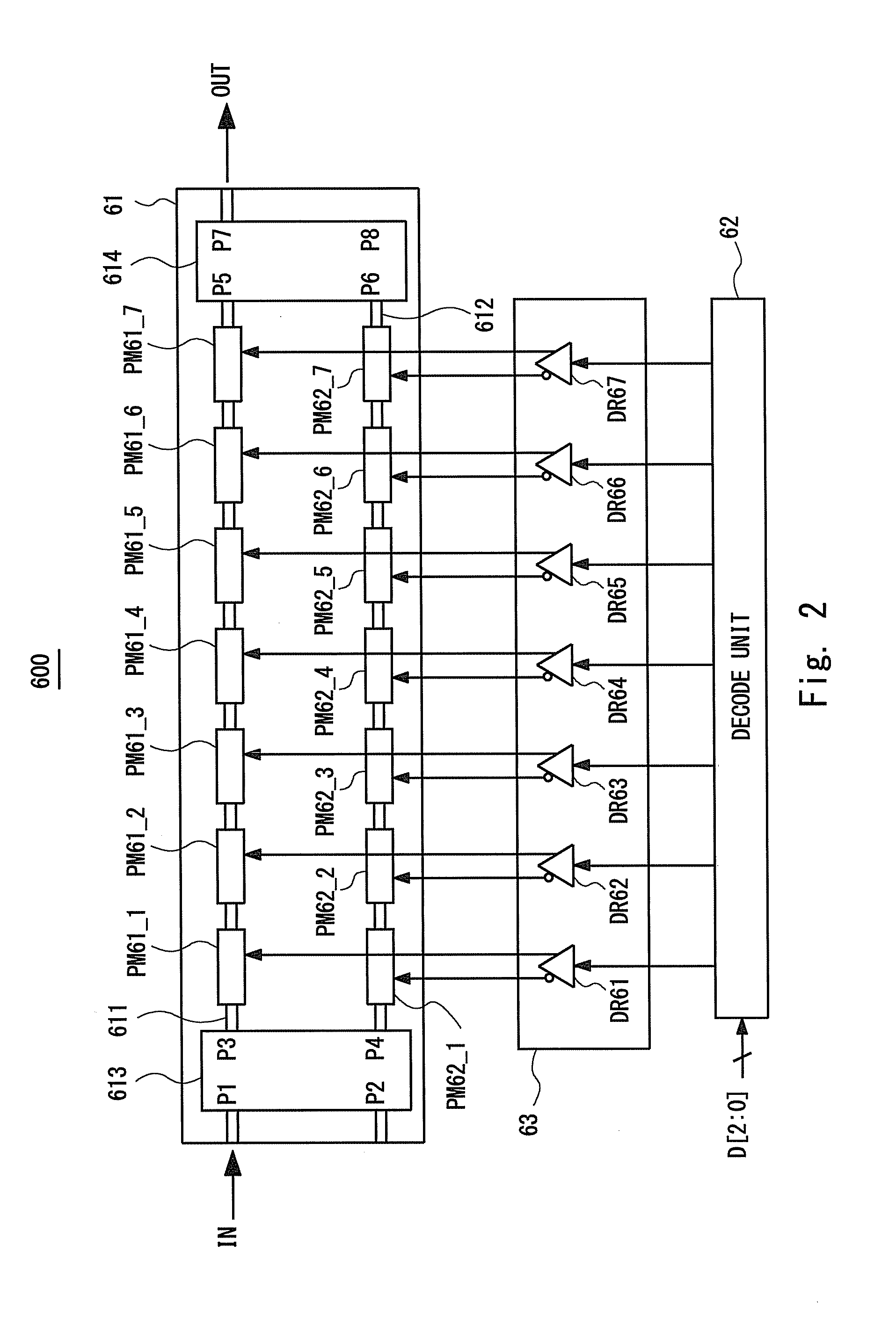
[0065]Next, the optical modulator 100 shall be described. The optical modulator 100 has the segmented electrode structure as in the case of the optical modulator ...

second embodiment

[0095]Next, an optical modulator 200 according to a second embodiment of the present invention shall be described. The optical modulator 200 is a specific example of the optical modulator 100 according to the second embodiment. FIG. 14 is a plane view schematically showing a configuration of the optical modulator 200. The determination circuit 13 includes a look-up table (LUT) 131 in the optical modulator 200.

[0096]The LUT 131 stores information associating the required transmission rate information INF with the drivers to be activated. The LUT 131 is stored in a memory device provided in the determination circuit 13. The LUT 131 may be stored in the determination circuit 13 in advance, input from the optical receptor or the optical transmission / reception system, or supplied as the setting information from the user.

[0097]FIG. 15 is a flowchart showing a method for deciding the activated driver in the optical modulator 200.

Step S201

[0098]The step S201 is the same as the step S101 of ...


PUM

PropertyMeasurementUnit
frequencyaaaaaaaaaa
transmission rateaaaaaaaaaa
phaseaaaaaaaaaa

Abstract

An optical modulation unit outputs an optical signal generated by binary-modulating an input light. Phase modulation areas are formed on an optical wave guide. A drive circuit includes a plurality of drivers outputting drive signals according to an input digital signal to the phase modulation areas. A determination circuit determines the driver to be activated among the plurality of the drivers based on information expressing a transmission rate. A driver control circuit activates the driver specified by a result of a determination of the determination circuit and cuts off power supply to the driver other than the activated driver. A switching circuit switches connections between the plurality of the drivers and the phase modulation areas. A switching control circuit that controls the switching circuit to cause the drive signals to be applied from the activated driver to the phase modulation areas.

Description

TECHNICAL FIELD[0001]The present invention relates to an optical modulator, an optical transmitter, an optical transmission / reception system, and a control method for an optical modulator.BACKGROUND ART[0002]With an explosive increase in demand of a broadband multimedia communication service such as the Internet or a high-definition digital TV broadcast, a dense wavelength-division multiplexing optical fiber communication system, which is suitable for a long-distance and large-capacity transmission and is highly reliable, has been introduced in trunk line networks and metropolitan area networks. In access networks, an optical fiber access service spreads rapidly. In such an optical fiber communication system, cost reduction for laying optical fibers as optical transmission lines and improvement of spectral efficiency per optical fiber are important. Therefore, a wavelength-division multiplexing technology which multiplexes multiple optical signals having different wavelengths is wid...

Claims


Application Information

Patent Timeline
Patent Type & Authority Applications(United States)
IPC IPC(8): G02F1/01H04B10/548
CPCG02F1/0121H04B10/548G02F1/011
Inventor NOGUCHI, HIDEMIYAMASE, TOMOYUKI
Owner NEC CORP
Why Eureka
Try Eureka