
Liquid crystal display device

Active Publication Date: 2015-11-19
FUJIFILM CORP
View PDF9 Cites 17 Cited by
  • Summary
  • Abstract
  • Description
  • Claims
  • Application Information

AI Technical Summary

Benefits of technology

The present invention relates to a liquid crystal display device that uses a specific light source unit with an improved emission intensity spectrum. The light source unit has blue, green, and red light emission peaks that provide a continuous and discontinuous emission in the visible light range. The light emitted has a local minimum and maximum in specific wavelength ranges. By controlling the phase difference of the protective film and the emission intensity spectrum of the light source unit, the display device can prevent the occurrence of rainbow-like unevenness and provide a high color reproduction. This invention improves the quality and performance of liquid crystal displays in high-temperature and high-humidity environments.

Problems solved by technology

However, liquid crystal display devices disclosed in JP-B-4962661 and JP-A-2012-256014 have a problem which a color reproducibility is low because they used a white color LED as a light source unit which emission intensity spectrum is sequentially.

Method used


Image

  • Liquid crystal display device
  • Liquid crystal display device
  • Liquid crystal display device

Examples


examples

[0136]Hereinafter, characteristics of the present invention will be described in more detail with reference to Examples. The materials, amounts, ratios, operations, order of operations, and the like shown in the Examples below may appropriately be modified without departing from the spirit of the present invention. Therefore, the scope of the present invention should not be construed as being limited by specific Examples shown below.

Manufacturing Examples

Preparation of Light Source Unit

(Light Source Unit Used in Example 1 and 9 and Comparative Example 1 and 6)

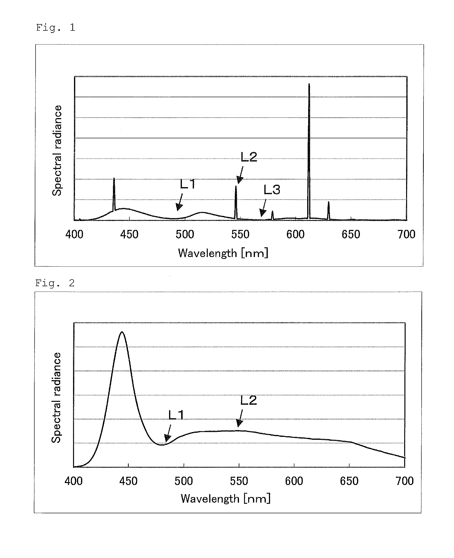
[0137]The light source unit of a liquid crystal TV manufactured by SONY Corporation “KDL-46W900A” which includes a blue color LED as a light source and a fluorescent substance including a quantum dot sealed in a glass tube disposed between the light source and a liquid crystal cell is used as alight source unit used in Example 1 and 9 and Comparative Example 1 and 6. An emission intensity spectrum of the light source unit was m...


PUM


Abstract

A liquid crystal display device has a light source unit and a liquid crystal cell sandwiched by two polarizing plates. The light emitted by the light source unit has separated peaks in each of blue, green and red wavelength ranges. The green and red peaks have a full width at half maximum intensity of 20 nm or more. At least one of the polarizing plates has a polarizer and a protective film with a Re of 5,000 nm or more and low moisture permeability. The device exhibits excellent color reproducibility and prevents display nonuniformity under a high temperature and high humidity environment.

Description

CROSS-REFERENCE TO RELATED APPLICATIONS[0001]This application claims priority under 35 U.S.C 119 to Japanese Patent Application No. 2014-99880 filed on May 13, 2014. The above application is hereby expressly incorporated by reference, in its entirety, into the present application.BACKGROUND OF THE INVENTION[0002]1. Field of the Invention[0003]The present invention relates to a liquid crystal display device. The present invention relates to a liquid crystal display device having a light source unit, a liquid crystal cell, a polarizer and a protective film in detail.[0004]2. Description of the Related Art[0005]Recently, use of Liquid Crystal Display, LCD, is enlarged and it is used for a TV, a monitor, a smart phone, a car navigation system, a digital camera, a digital signage and etc.[0006]A liquid crystal display device generally has polarizing plates on both a liquid crystal cell's viewing-side and a light source unit-side. A polarizing plate used for a liquid crystal display devic...

Claims


Application Information

Patent Timeline
IPC IPC(8): G02F1/1335G02F1/13363
CPCG02F1/133603G02F1/133528G02F2201/50G02F2001/133614G02F1/13363G02B5/3033G02F1/133614
Inventor YAMADA, NAOYOSHINAKAI, SHINICHIMIFUNE, MAKI
Owner FUJIFILM CORP
Learn More