Near field antenna for object detecting device

a technology of object detection and near field antenna, which is applied in the direction of instruments, measurement leads/probes, electromagnetic radiation sensing, etc., can solve the problems that the conventional rfid reader cannot determine the distance and location of the read rfid tags, and achieve good sensor sensitivity and high sensing accuracy

Active Publication Date: 2015-11-19
AUDEN TECHNO
View PDF0 Cites 196 Cited by
  • Summary
  • Abstract
  • Description
  • Claims
  • Application Information

AI Technical Summary

Benefits of technology

[0009]In summary, a near field antenna for an object detecting device is provided. The object detecting device could sense the units under test of the device under test through the near field antenna for obtaining the intensities of the...

Problems solved by technology

Accordingly, it raises an issue that the conventional RFID reade...

Method used


Image

  • Near field antenna for object detecting device
  • Near field antenna for object detecting device
  • Near field antenna for object detecting device

Examples


Embodiment Construction

[0018]The aforementioned illustrations and following detailed descriptions are exemplary for the purpose of further explaining the scope of the instant disclosure. Other objectives and advantages related to the instant disclosure will be illustrated in the subsequent descriptions and appended drawings.

[0019][An Embodiment of the Near Field Antenna]

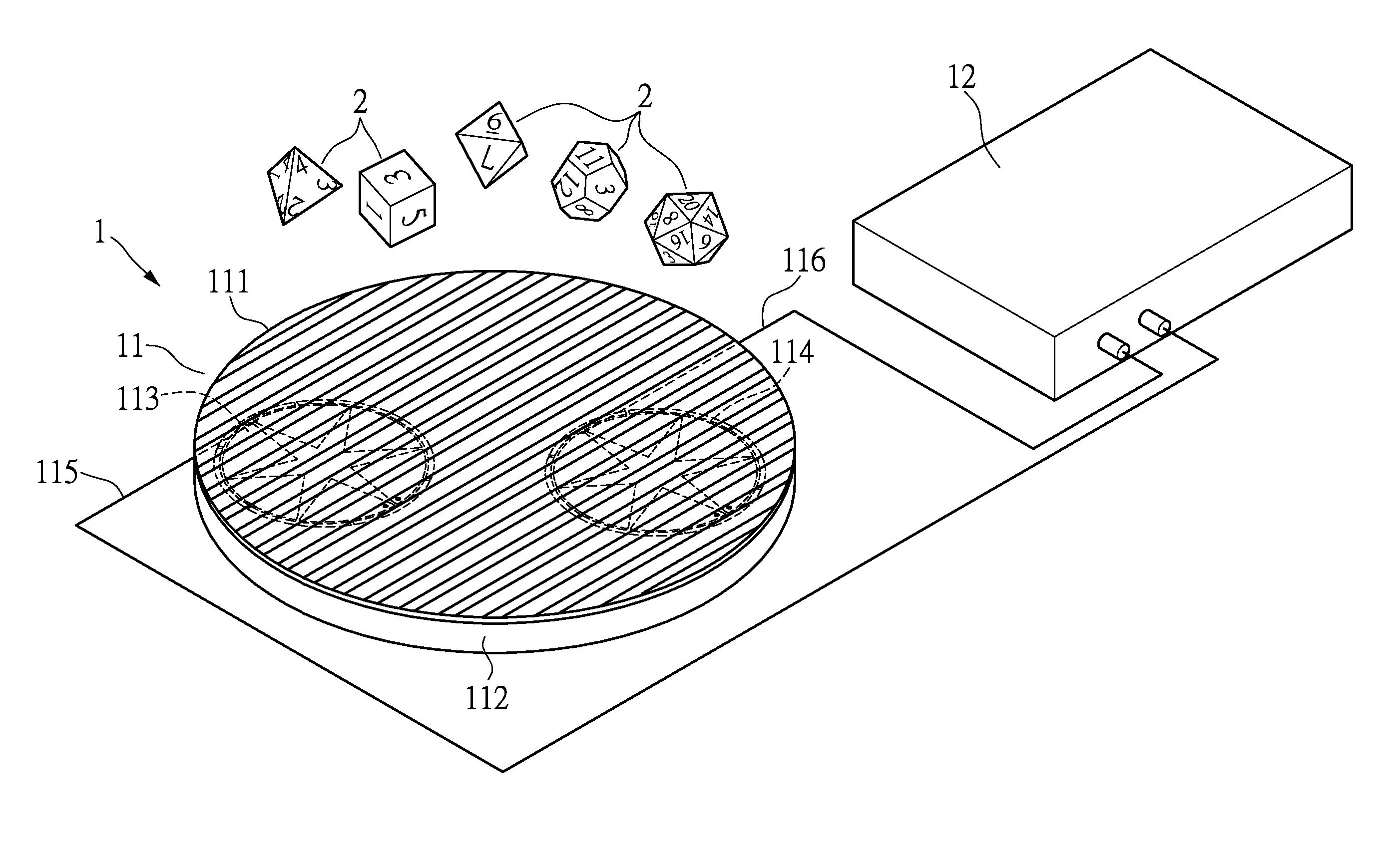
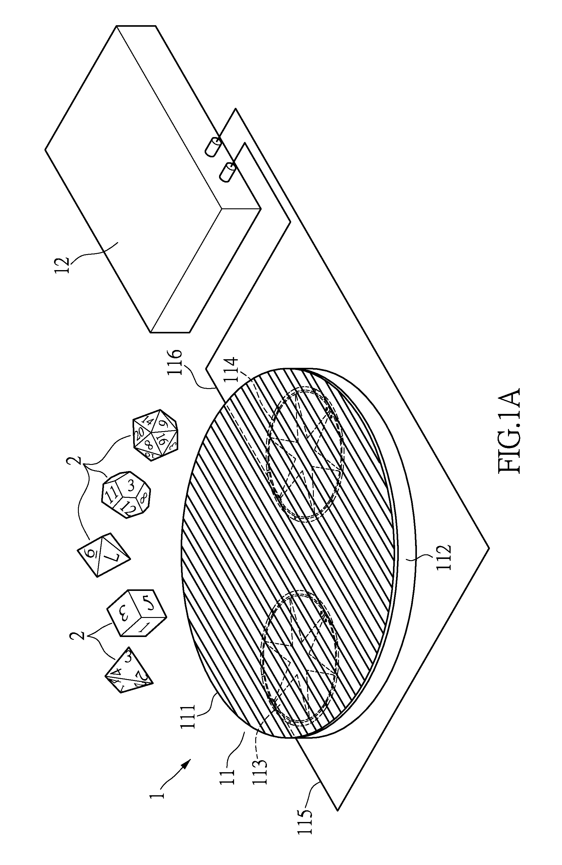
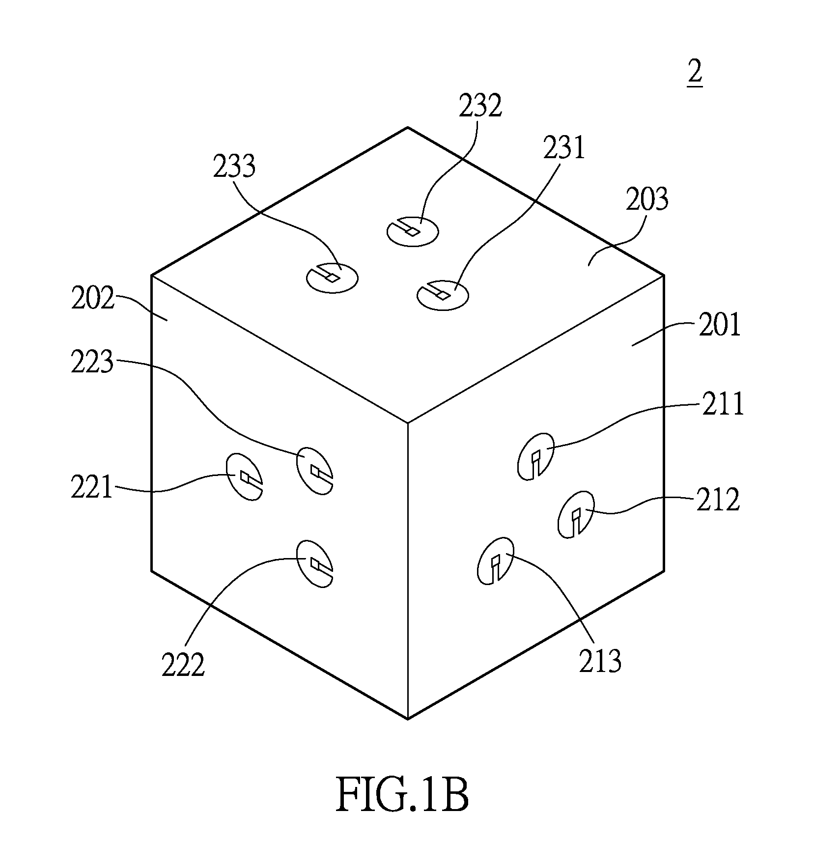
[0020]Please refer to FIG. 1A in conjunction with FIG. 1B, FIG. 1A shows a schematic diagram of an object detecting device according to an embodiment of the instant disclosure, FIG. 1B shows a schematic diagram of an object under test according to an embodiment of the instant disclosure. The near field antenna 11 is utilized for an object detecting device 1, for sensing a plurality of units under test (referring to the units under test 211, 212, 213, 221, 222, 223, 231, 232, 233) of at least an object under test 2. The units under test may be RFID tags for example. The object detecting device comprises the near field antenna 11 and a detec...


PUM


Abstract

A near field antenna adapted to an object detecting device, for sensing a plurality of units under test of at least an object under test. The near field antenna comprises a periodic guided-wave structure, a metallic reflection portion and at least two near field magnetic coupling antennas. The periodic guided-wave structure disposed below the object under test has a plurality of conductive units periodically arranged on a first plane. The metallic reflection portion is disposed under the periodic guided-wave structure to form an enclosed space. The near field magnetic coupling antennas are disposed on a second plane parallel to the periodic guided-wave structure, and are located in the enclosed space. The feed point and the ground point of each near field magnetic coupling antenna are fed by a coaxial cable with a feeding direction parallel to the periodically arranged conductive units.

Description

BACKGROUND OF THE INVENTION[0001]1. Field of the Invention[0002]The instant disclosure relates to an antenna; in particular, to a near field antenna for object detecting device.[0003]2. Description of Related Art[0004]The radio frequency identification tag (RFID tag) is utilized to be installed to an object for being detected through electromagnetic wave of wireless sensing means, which provides a fast and accurate detecting result. The application may be warehouse management or logistics for example. Radio frequency identification is a wireless communication technology which utilizes a reader and a tag to constitute a RFID system. The RFID reader transmits radio waves, and the RFID tag generates electric current according to electromagnetic induction of the radio waves. The generated electric current is for the operation of the chip (or integrated circuit) in the RFID tag and the RFID tag transmits electromagnetic wave responding to the RFID reader.[0005]The RFID reader is usually ...

Claims


Application Information

Patent Timeline
IPC IPC(8): H04B5/00G01R1/07G06K7/10H01Q19/10
CPCH04B5/0081G06K7/10336G01R1/07H01Q19/10H04B5/0012H04B5/0043H04B5/0062
Inventor YANG, CHENG-MINLIU, HSIEN-WEN
Owner AUDEN TECHNO
Why Eureka
Try Eureka