Relay System and Switching Device

a switching device and relay technology, applied in the field of relay systems and switching devices, can solve problems such as difficult to sufficiently grasp frame transfer paths, communication congestion, and network management, and achieve the effect of facilitating network managemen

Active Publication Date: 2015-11-19
APRESIA SYST LTD
View PDF2 Cites 3 Cited by
  • Summary
  • Abstract
  • Description
  • Claims
  • Application Information

AI Technical Summary

Benefits of technology

[0010]The present invention has been made in view of the problem above, and an object thereof is to provide a relay system and a switching device using a device-level redundancy capable of facilitating the network management.

Problems solved by technology

This may lead to communication congestion or the like due to flooding.
However, when the above-mentioned redundancy device to which the inter-device LAG is applied is disposed in such a carrier network, network management may become complicated.
For example, since the frames from the opposing L2 switching device to the redundancy device are distributed to the two L2 switching devices constituting the redundancy device with the LAG, it is not easy to sufficiently grasp the frame transfer paths.
Such a problem becomes severer as the number of incorporated switching devices increases like in a carrier network.

Method used


Image

  • Relay System and Switching Device
  • Relay System and Switching Device
  • Relay System and Switching Device

Examples


first embodiment

[0032]>

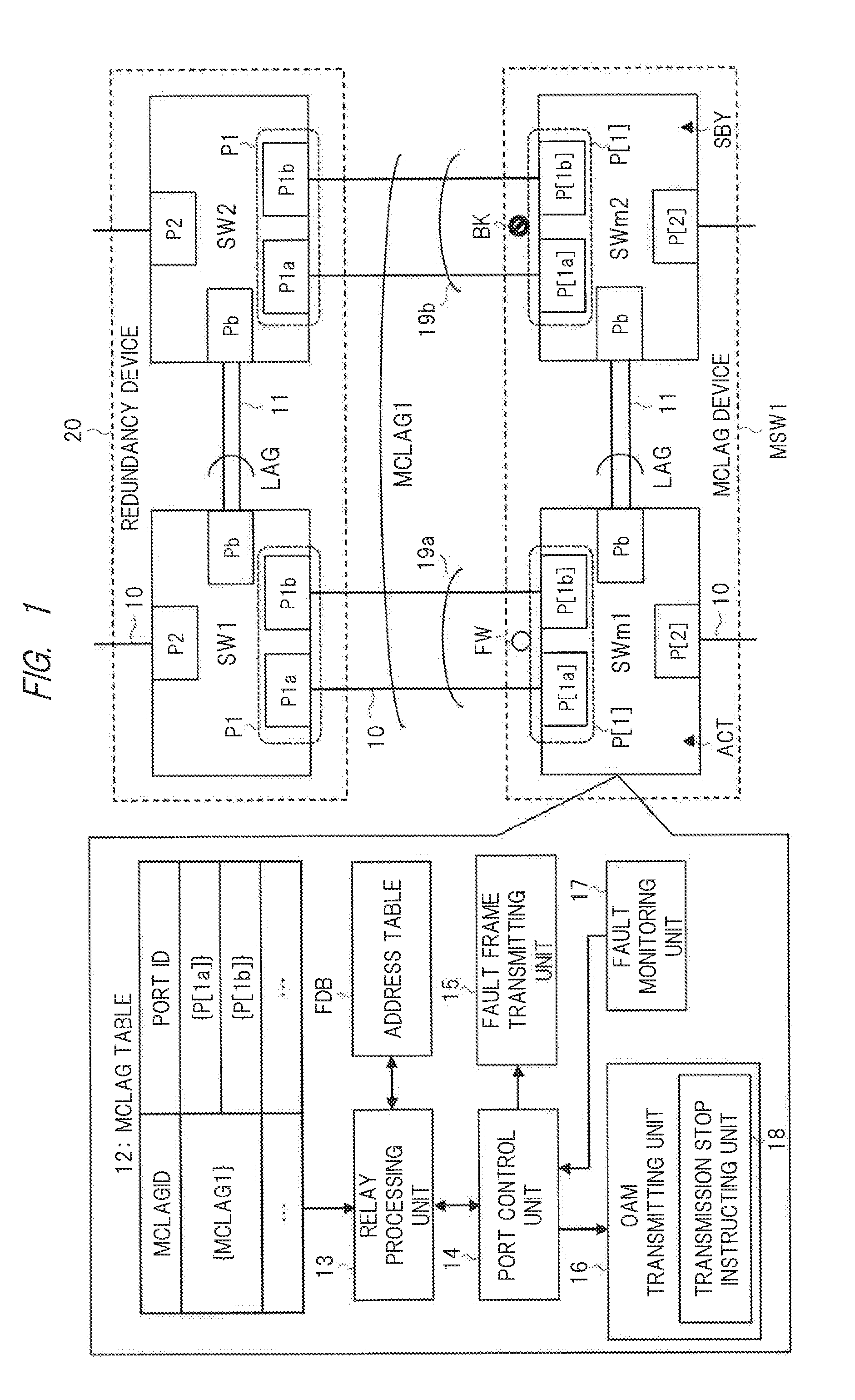
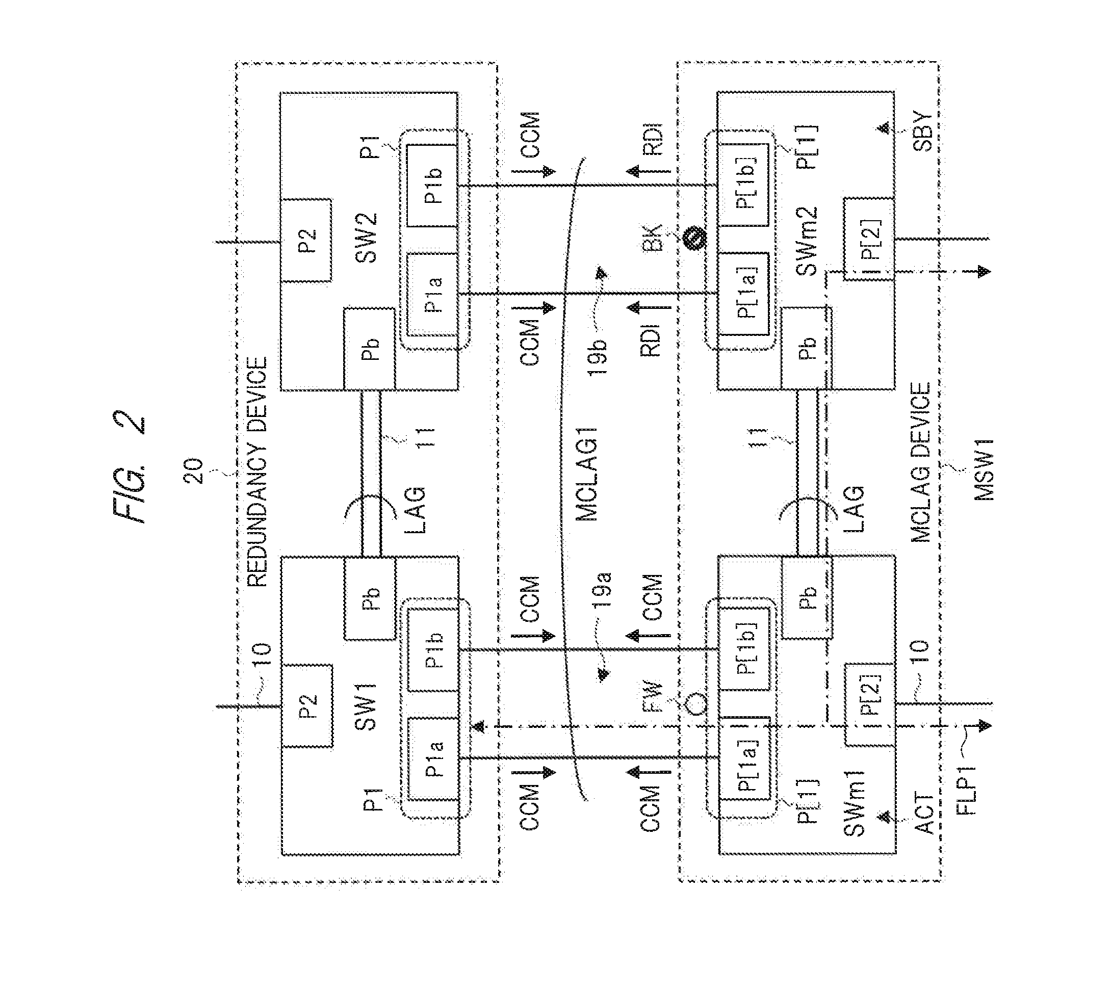
[0033]FIG. 1 is a schematic diagram of a configuration example of a relay system according to the first embodiment of the present invention. The relay system of FIG. 1 includes a MCLAG device (first redundancy device) MSW1 to which an inter-device LAG is applied and a redundancy device (second redundancy device) 20 to which an inter-device LAG is applied and which is connected to the MCLAG device MSW1. The MCLAG device MSW1 is made up of two L2 switching devices (first and second switching devices) SWm1 and SWm2 and the redundancy device 20 is also made up of two L2 switching devices (third and fourth switching devices) SW1 and SW2.

[0034]Each of the L2 switching devices SWm1 and SWm2 constituting the MCLAG device MSW1 has a MCLAG port group (first port group) P[1], a port (second port) P[2] and a bridge port Pb. The MCLAG port group P[1] is made up of one or a plurality of (in this case, two) MCLAG ports (first ports) P[1a] and P[1b]. The L2 switching device (first switching ...

second embodiment

[0110]>

[0111]FIG. 5 is a schematic diagram of a configuration example of a relay system according to the second embodiment of the present invention. The relay system shown in FIG. 5 is different from the relay system shown in FIG. 1 in that a MCLAG device MSW2 having the same configuration as that of the MCLAG device MSW1 is provided as the redundancy device 20 of FIG. 1. The MCLAG device MSW2 is made up of two L2 switching devices (third and fourth switching devices) SWm3 and SWm4.

[0112]Each of the L2 switching devices SWm3 and SWm4 constituting the MCLAG device MSW2 has a MCLAG port group P[1], a port P[2] and a bridge port Pb like the L2 switching devices SWm1 and SWm2. The MCLAG port group P[1] is made up of one or a plurality of (in this case, two) MCLAG ports P[1a] and P[1b]. The L2 switching device (third switching device) SWm3 and the L2 switching device (fourth switching device) SWm4 are connected by a communication line 11 via the bridge ports Pb.

[0113]The L2 switching dev...

third embodiment

[0147]In the third embodiment, details of the L2 switching devices of the first embodiment and the second embodiment will be described.

[0148]>

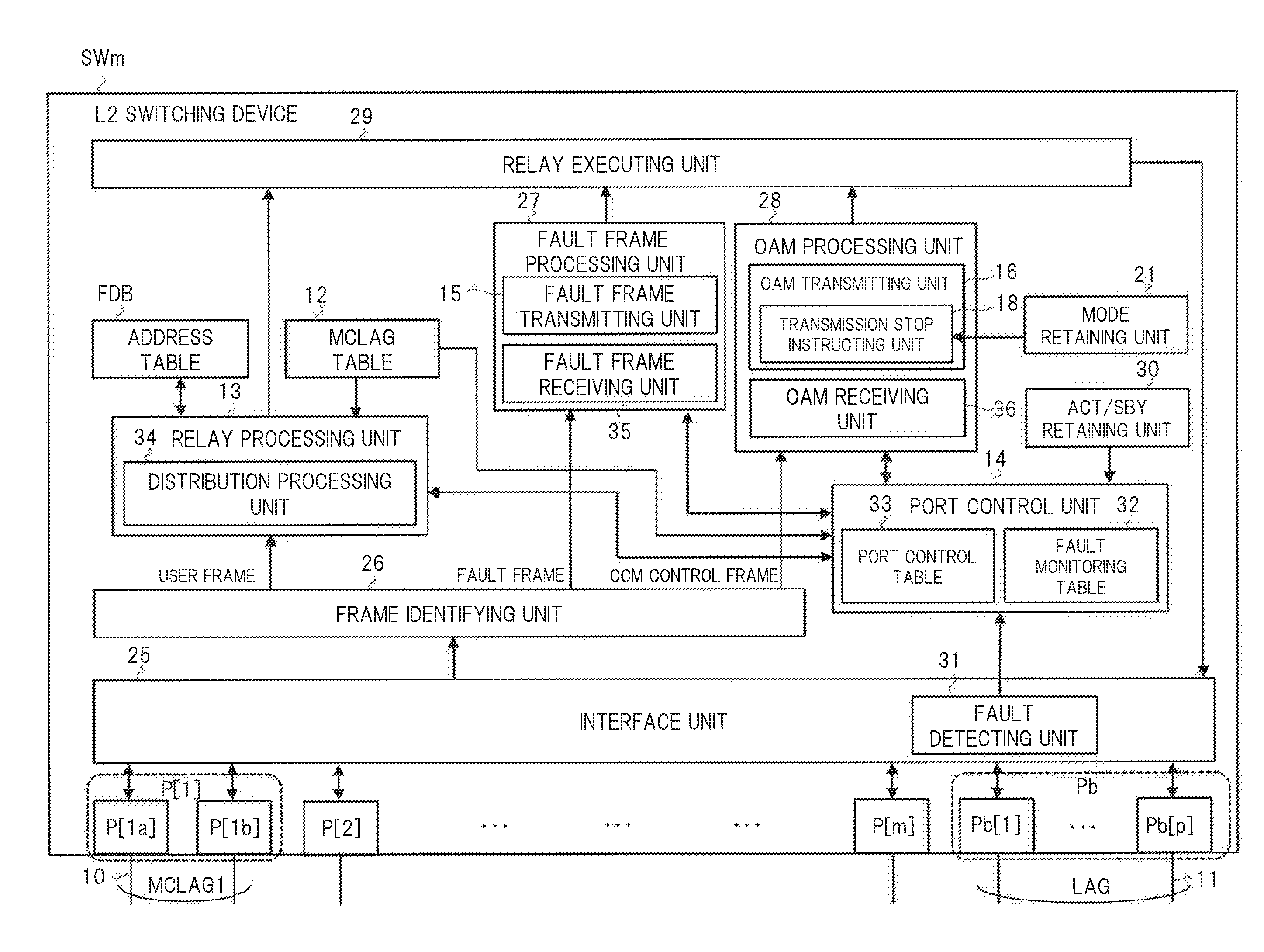
[0149]FIG. 10 is a block diagram showing a configuration example of the principal part of each switching device constituting a MCLAG device in a switching device according to the third embodiment of the present invention. Here, each of the L2 switching devices SWm1 to SWm4 constituting the MCLAG device in the relay system of FIG. 5 is taken as an example. FIG. 11A is a schematic diagram of a configuration example of the address table of FIG. 10, FIG. 11B is a schematic diagram of a configuration example of a fault monitoring table of FIG. 10, and FIG. 11C is a schematic diagram of a configuration example of a port control table of FIG. 10.

[0150]The L2 switching device (first or second switching device) SWm shown in FIG. 10 includes a MCLAG port group (first port group) P[1], a plurality of ports P[2] to P[m], the bridge port Pb, various proces...


PUM


Abstract

A first redundancy device and a second redundancy device connected to the first redundancy device are provided. A third switching device has a first link with a first port group of the first switching device and has no link with the second switching device. A fourth switching device has a second link with a first port group of the second switching device and has no link with the first switching device. Here, a communication between the first redundancy device and the second redundancy device is performed through the first link when the first link has no fault, and the communication is performed through the second link when the first link has a fault and the second link has no fault.

Description

CROSS-REFERENCE TO RELATED APPLICATION[0001]The present application claims priority from Japanese Patent Application No. 2014-100920 filed on May 14, 2014, the content of which is hereby incorporated by reference into this application.TECHNICAL FIELD OF THE INVENTION[0002]The present invention relates to a relay system and a switching device, for example, a relay system to which a device-level redundancy using two switching devices is applied.BACKGROUND OF THE INVENTION[0003]Japanese Patent Application Laid-Open Publication No. 2011-250185 (Patent Document 1) discloses a network system in which an inter-device link aggregation is set on each link between one network device and two network devices. When a fault occurs on a dedicated line connecting two network devices, an alternative path is established by using the link aggregation path. Also, two network devices are operated as an active system and a standby system for a control plane such as synchronization of path information bet...

Claims


Application Information

Patent Timeline
Patent Type & Authority Applications(United States)
IPC IPC(8): H04L12/24H04L12/26H04L12/939H04L12/707H04L45/24H04L45/247H04L45/586
CPCH04L41/0668H04L49/552H04L43/0817H04L45/22H04L12/4625H04L45/24H04L49/15H04L49/25H04L12/46
Inventor YASUDA, MAKOTOTSUBOTA, SHIGERU
Owner APRESIA SYST LTD
Why Eureka
Try Eureka