Method for Conducting Redundancy Checks in a Chain Network

a chain network and redundancy check technology, applied in data switching networks, frequency-division multiplexes, instruments, etc., can solve the problems of increasing the burden on the microprocessors of the network devices, the instability of the mac address of the network device, and the loss of enterprises, so as to facilitate network management, enhance the reliability of the chain network, and quickly recover the network

Active Publication Date: 2010-11-25
MOXA INC
View PDF3 Cites 5 Cited by
  • Summary
  • Abstract
  • Description
  • Claims
  • Application Information

AI Technical Summary

Benefits of technology

[0012]The primary object of the present invention is to control communication of switches with an external network at both ends, so that the communication port of the first switch is forwarding, while the second switch sets its communication port to be blocking, when the chain network is in a normal operational state. In this context, the chain network will communicate with a external network via the communication port of the first switch. When the chain network is break, the two switches close to the break point will send control packets to the first and second switches respectively, so as to forwarding the communication port that is originally blocking and recover the communication to the external network. As the first switch or second switch is directly set to be forwarding, it is not necessary to recalculate the best path for network execution in the process of recovering the chain network from its outage, thus recover the network quickly in the chain network architecture. On one hand, this will enhance the reliability of the chain network, and on the other hand, this will facilitate network management.
[0013]Another primary object of the present invention lies in the way to set the communication ports state for the first or second switches of the chain network themselves, the original settings for the existed networks architecture that the chain network attach to do not have to be changed.
[0014]At this moment, it is not necessary to establish a complex coordinating mechanism between the chain networks and the other external ones, either. Instead, the newly-added chain networks can operate directly by connecting their first and second switches with the original network architecture for network expansion. This method will achieve the effects of including many network nodes in a single network architecture, increased extendibility and inconvenience.
[0015]The secondary object of the present invention lies in use of the first or second switch of a chain network for communication with external networks, which may be external redundant networks. And when the chain network and the external redundant networks transmit packets to each other, the first or second switch can be utilized to block redundancy control packets from the external networks. By doing so, many different redundancy mechanisms may be included in a single network architecture and do not interfere with each other, thus increasing compatibility of these networks.
[0016]A further object of the present invention is to ensure that when a single or plurality of chain networks are connected with external network devices or external redundancy network structures, it is not necessary to connect the first switch of each chain network with its second switch. If a network break occurs, the two switches close the break point will send packets to the first and second switches at the same time, thus saving communication ports and network cables and reducing high costs in equipment construction for enterprises.

Problems solved by technology

However, due to instability of network devices, production may be interrupted, causing heavy losses to enterprises.
However, the presence of these backup devices will easily cause looping of the network, which will further lead to such problems as broadcast storm, simultaneous receipt of the same packets by a single network device and instability of the MAC address of the network device.
Under such circumstance, switches will learn and change the address uninterruptedly, and the burden on microprocessors of the network devices will increase.
Yet in an STP environment, when it is necessary to start backup devices in response to any network device failure, it will take longer recalculation time to recover the network to its normal state.
If the tree topology is too big with too many network devices (i.e. network nodes), it will cause the backup devices to respond at a lower speed.
For practical applications of industrial control devices, once the network crash long time, it will cause heavy losses or serious incidents.
Recently, the industry environment often uses a ring network; however, when a redundancy technology be set up in the ring network, the increasing node of the ring network occurs higher recovery time and lower reliability, Therefore, multi ring network topology is adopted to meet the requirements for quicker recovery capability and more network nodes in a single network.
Though the above-mentioned network recovery capability is more effective than STP and RSTP, however, the ring coupling system is more complex to set up between the ring networks and reduce network reliability.
Compared to the strict requirement for network stability in industrial control, the reliability of such network operation is rather low.
And if this redundancy mechanism is adopted by enterprises in ring networks for production and manufacture, it will increase the risks that network devices are incompatible with each other and cannot transmit data among them or the machine cannot work continuously.

Method used


Image

  • Method for Conducting Redundancy Checks in a Chain Network
  • Method for Conducting Redundancy Checks in a Chain Network
  • Method for Conducting Redundancy Checks in a Chain Network

Examples


Embodiment Construction

[0025]To achieve the objects and effects stated above as well as the technology and framework adopted in the present invention, some examples of the preferred embodiments of the present invention are given with reference to the accompanying drawings to describe the features and functions of the present invention in detail.

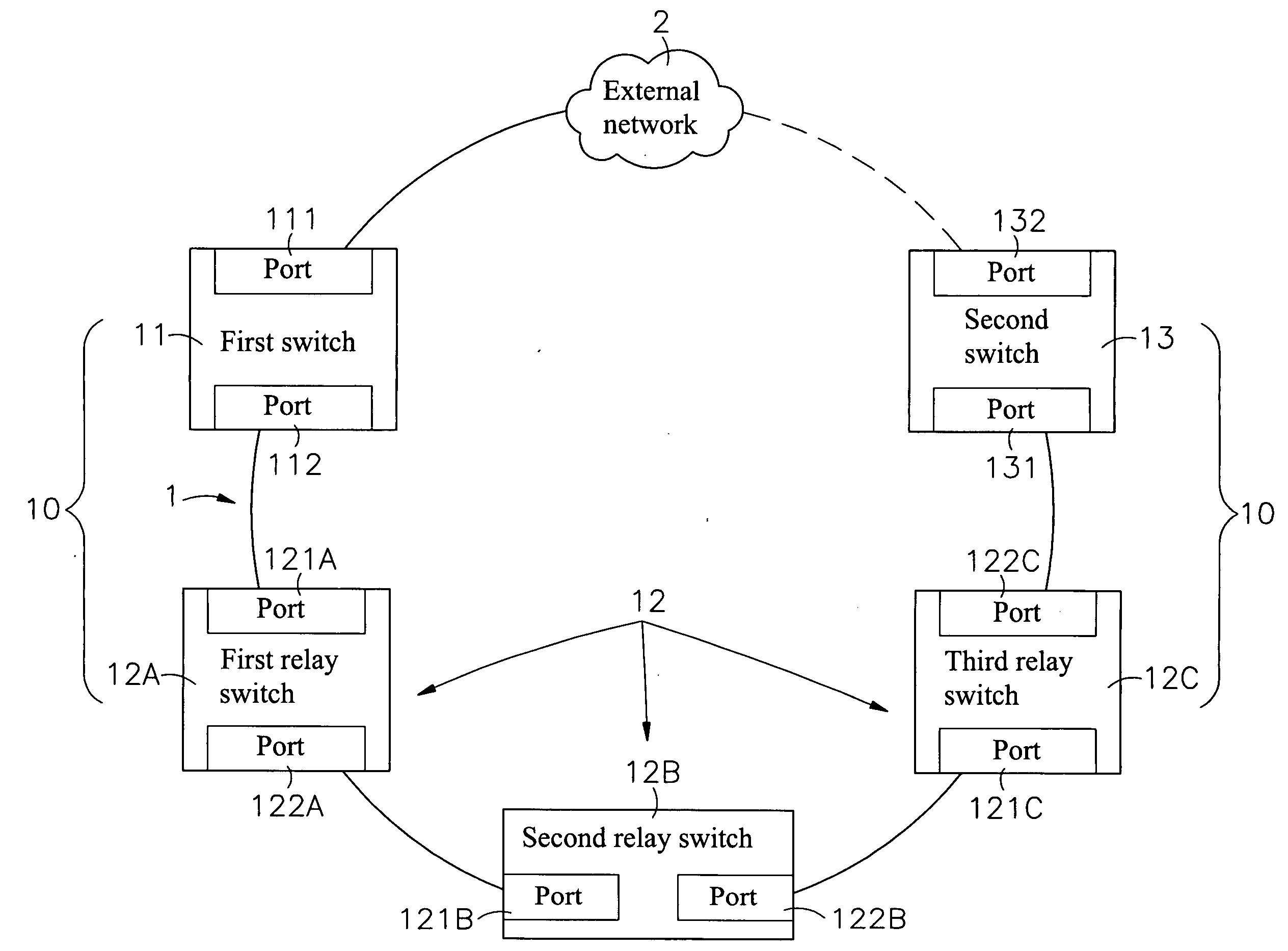
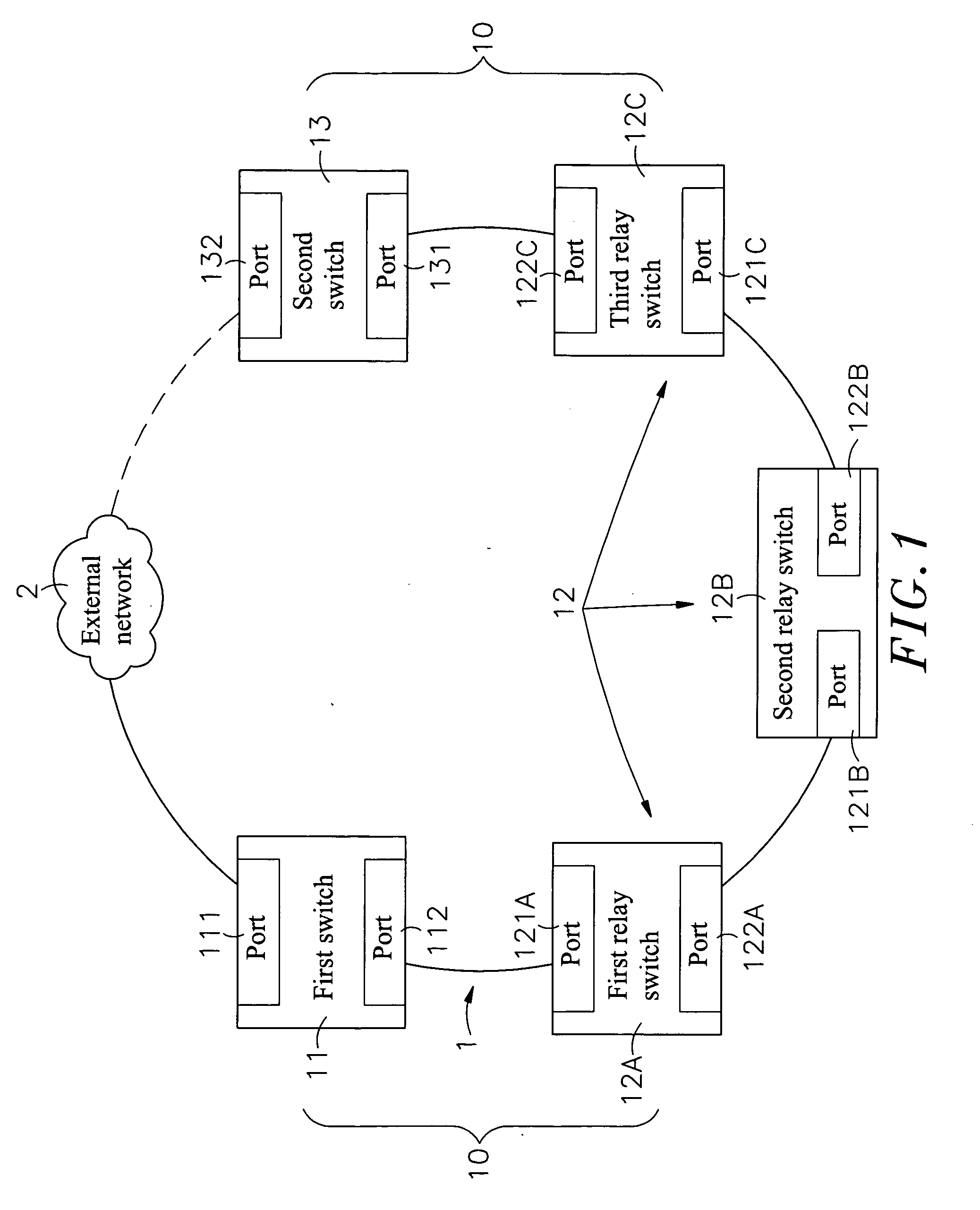
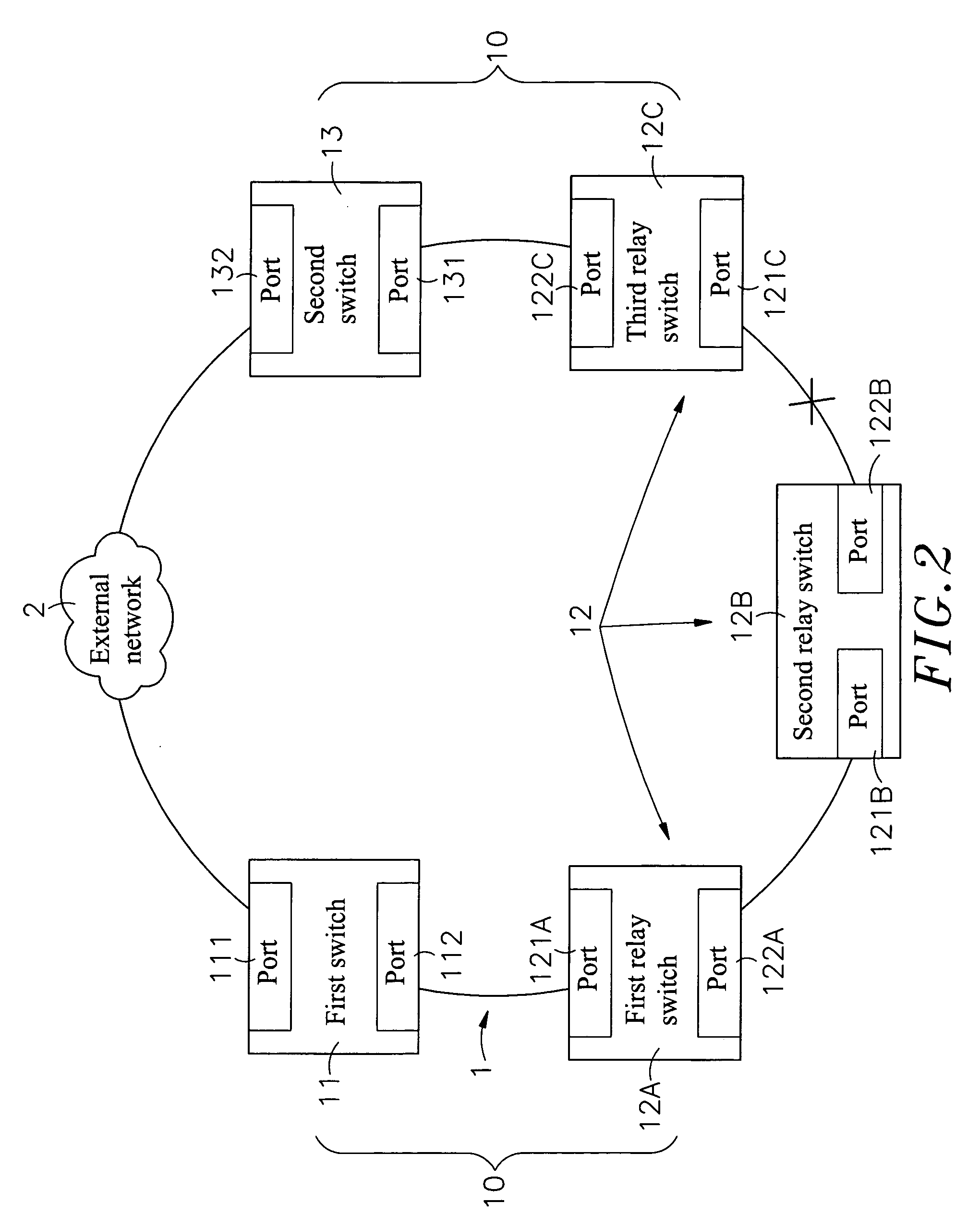
[0026]Refer to FIG. 1, which shows the architecture of a chain network 1 of the present invention, including a plurality of switches 10, and each of these switches includes a first switch 11, a relay switch 12 and a second switch 13, wherein:

[0027]The first switch 11 and the second switch 13 are located at two opposite ends of the chain network 1, and the relay switch 12 lies between the first switch 11 and the second switch 13, wherein the first switch 11, second switch 13 and relay switch 12 may include two or more ports. For the present invention, two ports are considered in examples of the embodiments and there may be one or more relay switches 12. However, the...


PUM


Abstract

The present invention relates to a method for conducting redundancy checks in a chain network, wherein the two ends of the chain network are equipped with a first switch and a second switch respectively, and a port of the first or second switch used for communicating with an external network is set to be blocked, so that when an link failure happens to any switch of the chain network, the two switches close to the link failure port sends control packets to the first and second switches respectively to forward the port that is originally blocking, thus making the network to return to normal state quickly. Besides, as the first and second switches are used to connect other chain networks, external network devices or external redundant network architectures, it allows more network nodes to be included in single network architecture and provides flexibility and compatibility in use by including different redundancy mechanisms.

Description

[0001]This application claims the priority benefit of Taiwan patent application number 098116952, filed on May 21, 2009.BACKGROUND OF THE INVENTION[0002]1. Field of the Invention[0003]The present invention relates to a method for conducting redundancy checks in a chain network, more particularly, to establishment of a redundancy mechanism in the chain network, in which the communication ports of a first switch and a second switch are set to be forwarding and blocking respectively, so that when an link break happens to the chain network, the two switches close to the break point will send control packets to the first and second switches respectively to forwarding the port that is originally blocking, thus allowing the network to return to normal state quickly.[0004]2. Description of the Prior Art[0005]With quick changes in IT and vigorous developments on Internet technologies, network technologies are utilized to help people to communicate with each other beyond boundaries. Progress ...

Claims


Application Information

Patent Timeline
Patent Type & Authority Applications(United States)
IPC IPC(8): G06F11/00
CPCH04L12/40169
Inventor LING, MING-HUANGCHEN, MING-CHUANG
Owner MOXA INC
Why Eureka
Try Eureka